
Remote power feed method and system

a technology of remote power and feed method, applied in data switching networks, instruments, high-level techniques, etc., can solve the problems of reducing power-feeding efficiency and providing necessary power, and achieve the effect of dramatic improvement of remote power feeding efficiency

Inactive Publication Date: 2005-01-25
NEC CORP
View PDF19 Cites 112 Cited by
  • Summary
  • Abstract
  • Description
  • Claims
  • Application Information

AI Technical Summary

Benefits of technology

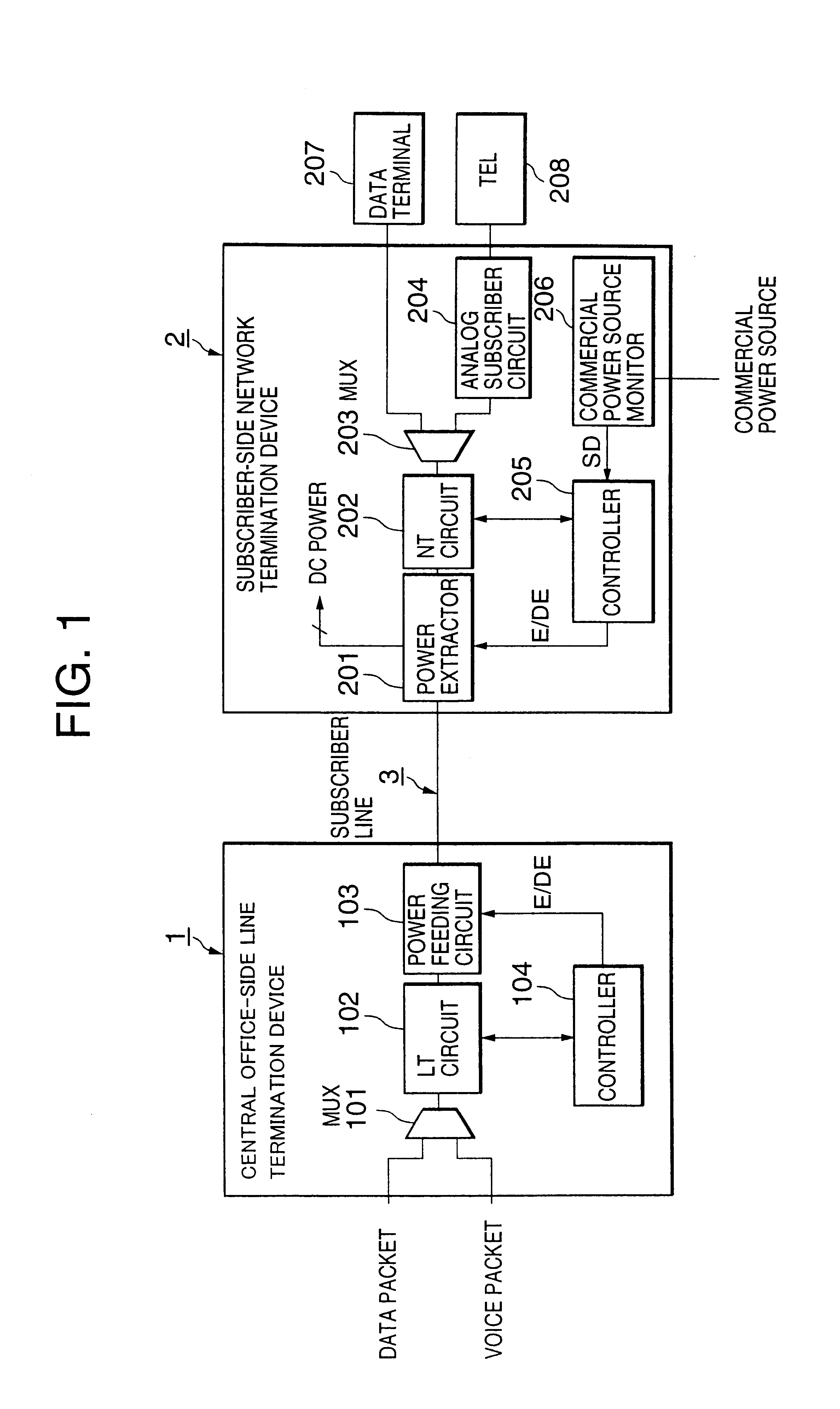
An object of the present invention is to provide a remote power feed method and system allowing efficient remote power feeding into a network termination device even when a power failure occurs at a subscriber site.
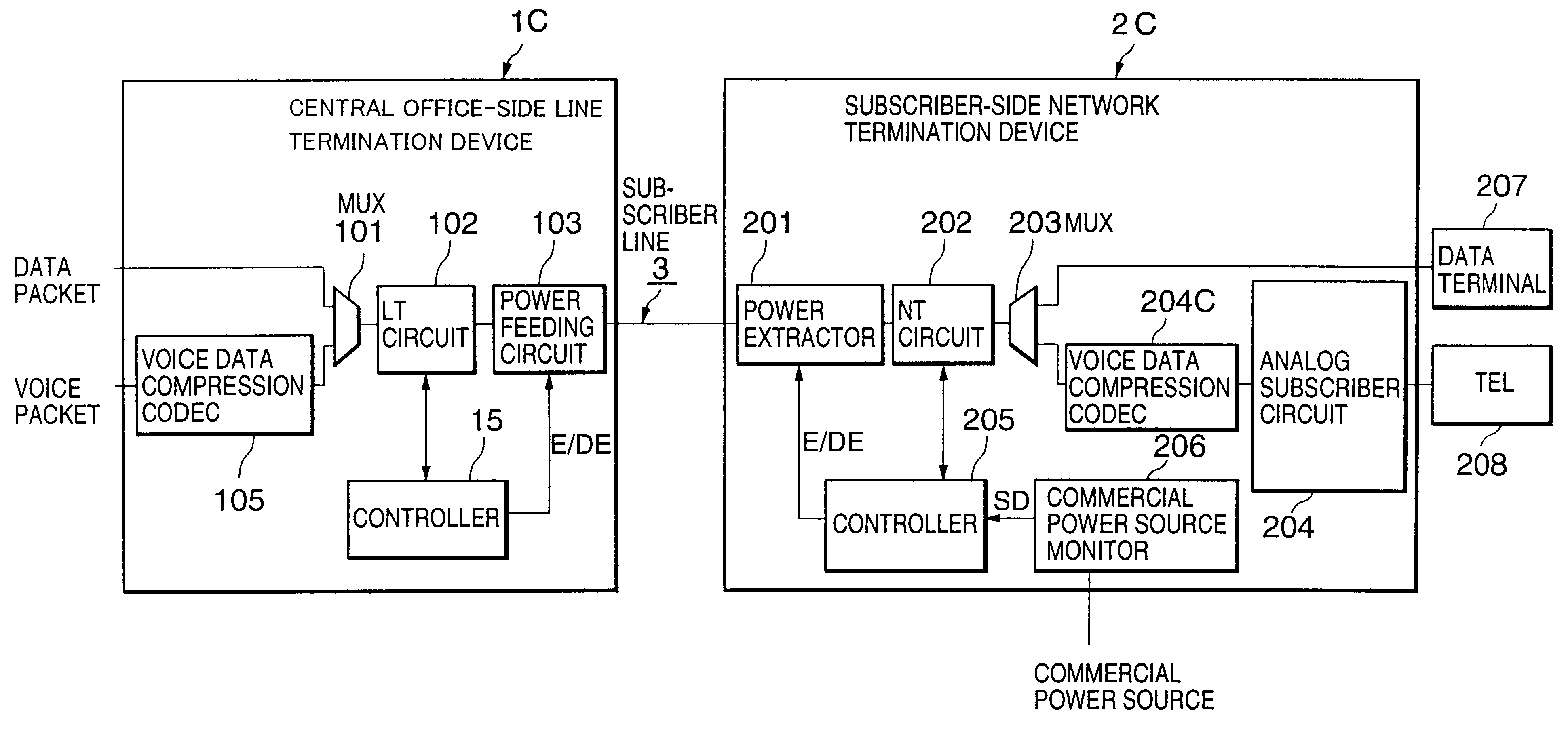
Another object of the present invention is to provide a remote power feed method and system allowing efficient remote power feeding into a network termination device even when a power failure occurs at a subscriber site while ensuring at least voice communication service.
Further, since the remote power feeding into the subscriber line is performed only when commercial power failure occurs, the remote power feeding efficiency is expected to be dramatically improved.

Problems solved by technology

However, such a large-capacity battery can provide necessary power for only a limited time period.
Such a power feed system from network to subscriber, however, causes high power losses due to the high impedance of a subscriber line, reducing power-feeding efficiency.

Method used


Image

  • Remote power feed method and system
  • Remote power feed method and system
  • Remote power feed method and system

Examples


Embodiment Construction

In the following embodiments, a high-speed digital interface such as ADSL or SBSL is used to transmit voice packets and thereby a subscriber can obtain the telephone service.

Referring to FIG. 1, a subscriber line system includes a central office-side line termination device 1, a subscriber-side network termination device 2, which are connected through a subscriber line 3 providing the DSL service. As described later, the subscriber-side network termination device 2 has a power failure detecting and notifying function and a line-power receiving function. The central office-side line termination device 1 has a line-power feeding function depending on whether a power failure occurs at the subscriber-side network termination device 2.

Central Office-side Line Termination Device

The central office-side line termination device 1 includes a multiplexer / demultiplexer (hereafter, simply called “MUX”) 101, a line termination circuit 102, a remote power feeding circuit 103, a controller 104, and...


PUM


Abstract

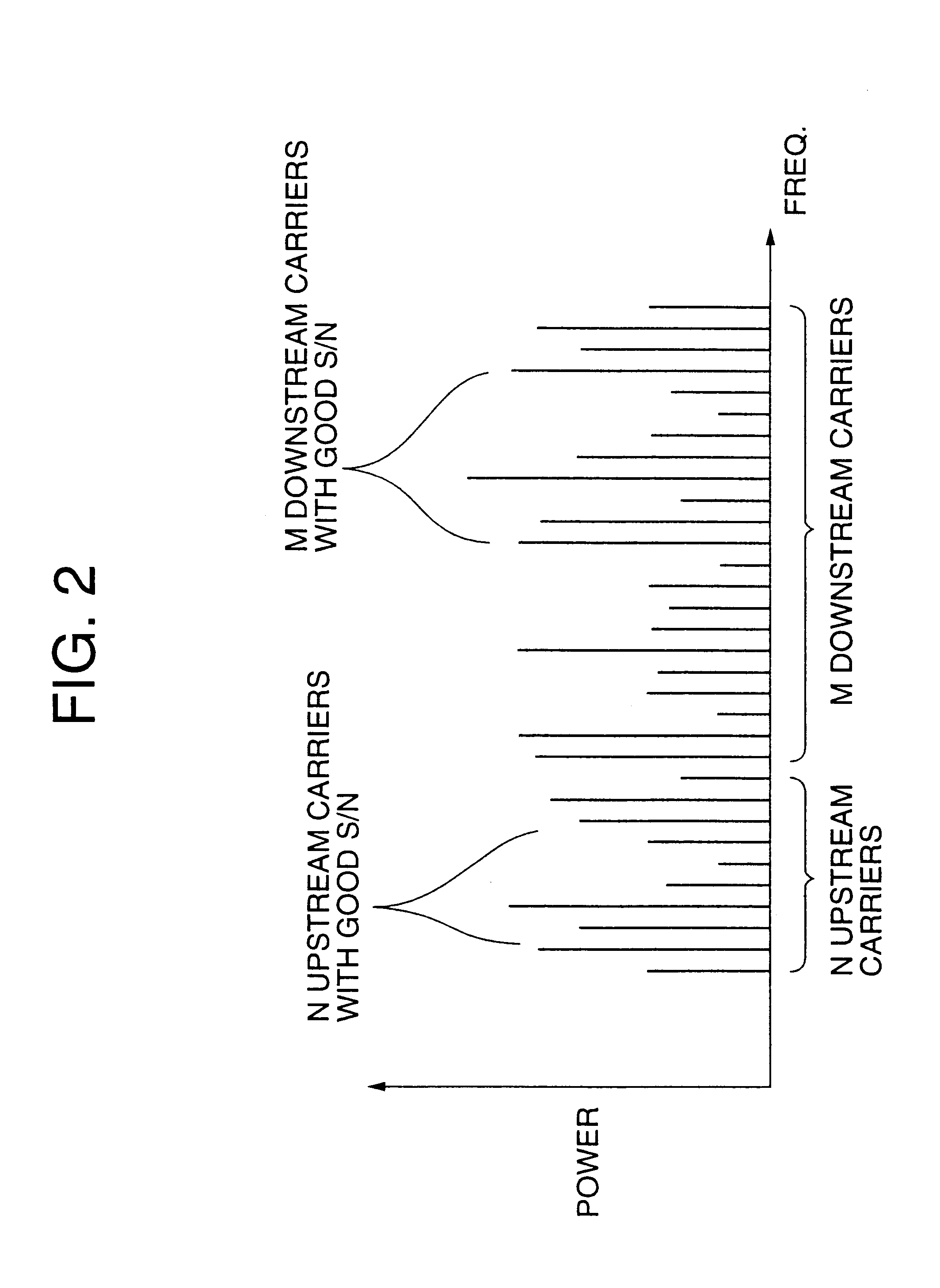
A remote power feeding method allowing efficient remote power feeding into a network termination device in the event of a commercial power failure at a subscriber site is disclosed. When the commercial power failure occurs, a power failure signal is transmitted from the subscriber-side network termination device to the central office-side line termination device. The central office-side line termination device, when receiving the power failure signal, starts DC power feeding to the subscriber-side network termination device via the subscriber line. During the power failure, only voice communication is permitted using previously selected good channels.

Description

BACKGROUND OF THE INVENTION1. Field of the InventionThe present invention relates to a method and system for feeding electrical power to a network termination device required for a DSL (Digital Subscriber Line) service.2. Description of the Related ArtWith the wide use of digital switching systems, an increasing number of DSL network termination devices for DSL service are installed at subscriber sites. The DSL technology dramatically increases the digital capacity of ordinary subscriber lines into the subscriber site, that is, home or office. DSL includes two types of usage: Asymmetric DSL (ADSL) and Symmetric DSL (SDSL or HDSL). ADSL is used for Internet access, where fast downstream Is required, but slow upstream is acceptable. SDSL is designed for short haul connections that require high speed in both directions.In the case where the electrical power fed into a DSL network termination device fails or drops to an unacceptable voltage level, it is necessary to feed necessary power...

Claims


Application Information

Patent Timeline
IPC IPC(8): H04L12/10H04M19/08H04M19/00H04L12/70H04M3/00H04M11/06
CPCH04L12/10H04M19/08H04M19/005Y02D30/70
Inventor HIRAOKA, TOSHIHIDE
Owner NEC CORP
Learn More