Method and system for improving pattern recognition system performance

a pattern recognition and performance improvement technology, applied in the field of pattern recognition systems, can solve the problems of insufficient real-world application, complex and cumbersome approaches, and system not designed to perform error-free decisions, and achieve the effect of increasing the robustness of the recognition system and more system robustness

Inactive Publication Date: 2005-01-25
NORTHEAST PHOTOSCI
View PDF16 Cites 44 Cited by
  • Summary
  • Abstract
  • Description
  • Claims
  • Application Information

AI Technical Summary

Benefits of technology

A preferred embodiment approach to increasing the robustness of the recognition systems is to erect a margin or “guard band” around the decision boundary or threshold. A very robust system is a measure of the “distance” that the boundary would have to move (the margin) to include the nearest object that would be an instance of error. The width of that band is a figure of merit for generalizability of the discriminant and decision boundary and wider margins offer more system robustness.
The present invention allows the user in preferred embodiments to define margins at each decision level. In this way, when the classifier is applied to unknowns, those unknowns determined to be of a specific class will also have a confidence level associated with them. However, there may be items that will be unclassified within such margins.
It is a feature and advantage of the present system that the process can be used iteratively until all the items in question are properly classified, or until some allowable unclassified amount remains. It is an advantageous feature of the present invention that if a particular discriminant is used, for example a function of weight, to classify much of the population being considered, that same parameter, weight, can be used again and again to further isolate portions of the population by using different decision boundaries in each use. Moreover, it is another feature of the present invention that a discriminant boundary decision that poorly separates objects in the population is still useful and workable if some, albeit, small portion of the population is separated and thus eliminated from further consideration. Still another feature of the present invention is that the parameters used in the inventive process need not be independent from each other. Yet another advantage is that it is possible to insert a margin between classes to allow for more robust decisions for objects not in the training sets. Still yet another advantage is that after the discriminant spaces, decision boundaries and rules are trained sequentially, they can be applied in parallel in some cases. Also, continual updating of the recognition system in light of behavior of the system on new, un-trained-on data is straightforward. A most useful property of the present invention is that this invention can be viewed as a way of making existing pattern recognition systems work better preserving the benefits of presently installed systems, but allowing for significantly improved performance. This removes many of the practical and psychological barriers of present users.

Problems solved by technology

Moreover, the system is not designed to perform error free decision making.
A logical limitation of the PCA approach is that once a discriminant has correctly identified some of the items it is unnecessary to apply a second discriminant to those items.
However, this method is complex in practice and will not guaranty that the training set is classified error free.
But as training sets become large this approach becomes complex and cumbersome.
This approach has another limitation in that the discriminants used are not the minimum necessary to classify all the members of the training set.
However, a limitation of this filter is that it is applicable only to problems solvable with a linear discriminant and therefore inadequate for most real applications.
But, these systems produce errors when analyzing new data, and improved performance is desirable.
However, improvements that require significant investments in time, people and money are often not available to the users.

Method used


Image

  • Method and system for improving pattern recognition system performance
  • Method and system for improving pattern recognition system performance
  • Method and system for improving pattern recognition system performance

Examples


Embodiment Construction

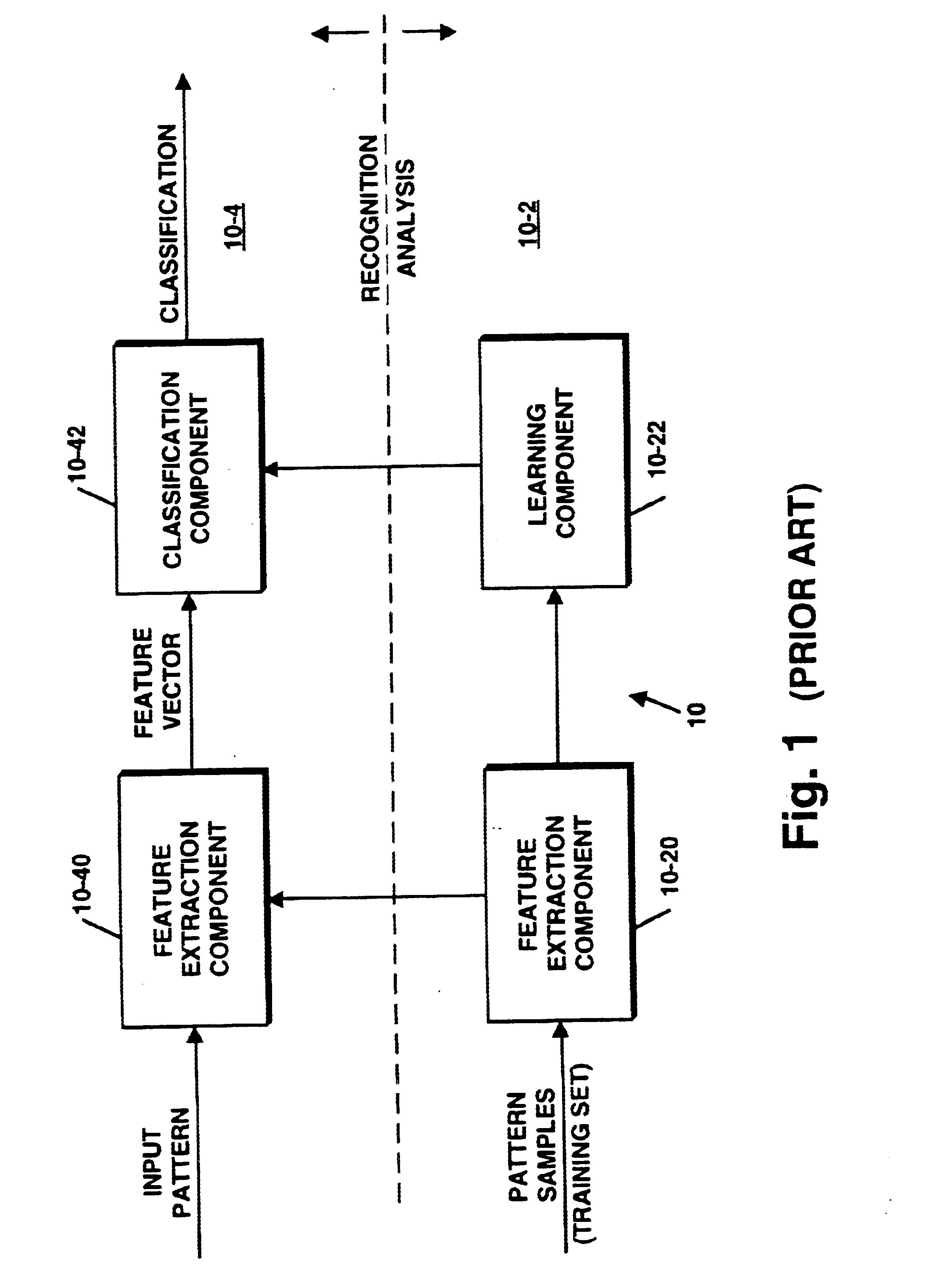
FIG. 1 is a block diagram of a conventional pattern recognition system 10 that includes two major sections 10-2 and 10-4. Section 10-2 performs an analysis function while section 10-4 performs the recognition function. As shown, section 10-2 includes a feature selection component 10-20 and a learning component 10-22. Section 10-4 includes a feature extraction component 1040 and a classification component 10-42.

Feature Extraction and Section Components

As known in the art, what features are extracted and how this is accomplished depend on the patterns and the number of classes under scrutiny. Generally, extraction and selection methods follow one of two types of schemes. A first scheme is feature space transformation process wherein the system components transform original feature space into lower dimensional spaces for pattern representation and / or class discrimination. In the case of pattern representation, systems often use least-mean-square error and entropy criteria in determinin...


PUM


Abstract

Stand-alone or assistive pattern recognition system and process enabling error free classification of all objects in a training set and application to unclassified objects. Parameters and / or features of the data objects in a training set are selected and measured, from which discriminants are computed. The measured data is plotted in discriminant space and decision boundaries or thresholds determined, preferably such that at least one object from one class is isolated from the remaining objects, removed from the training set, and the process repeated until an acceptable number of unclassified objects remain. The system can be applied sequentially to classify all the members of the training set belonging to one class and then applied to objects in other classes. Fuzzy quantifiable determinations of an object's likelihood of class membership can be made. Objects' positions and classifications are obtainable in an optical system using Fourier techniques without limitation to linearly discriminable problems.

Description

FIELD OF THE INVENTIONThe present invention relates to pattern recognition systems, and, more particularly to methods and systems for improving the performance of such systems.BACKGROUND OF THE INVENTIONPattern recognition systems have been designed and built for everything from character recognition, target detection, medical diagnosis, analysis of biomedical signals and images, remote sensing and identification of human faces and fingerprints, to reliability, socio-economics, archaelogy, speech recognition, machine part recognition and in industrial applications such as automatic inspection of industrial products such as semiconductor chips for defects.As well known in the art, pattern recognition often begins with some kind of preprocessing to remove noise and redundancy in measurements taken from physical or mental processes to ensure an effective and efficient pattern description. Next, a set of characteristic measurements, numerical and / or non-numerical and relations among the...

Claims


Application Information

Patent Timeline
Patent Type & Authority Patents(United States)
IPC IPC(8): G06K9/62G06K9/74
CPCG06K9/741G06K9/6256G06V10/89G06F18/214
Inventor CAULFIELD, H. JOHN
Owner NORTHEAST PHOTOSCI
Why Eureka
Try Eureka