Image processing system, image processing apparatus, image input apparatus, image output apparatus and method, and storage medium

Inactive Publication Date: 2005-01-25
CANON KK
View PDF6 Cites 50 Cited by
  • Summary
  • Abstract
  • Description
  • Claims
  • Application Information

AI Technical Summary

Benefits of technology

Furthermore, the second output means selectively outputs a code sequence that gradually improves spatial resolution

Problems solved by technology

However, the image data volume becomes huge with increasing resolution, and a long transfer time is often required.
Hence, the coding and storage processes require a large storage size.
However, some problems are experienced in an image decoding apparatus that decodes encoded data generated by the conventional scalable encoding method mentioned above.
Furthermore, when arithmetic coding is used upon encodi

Method used


Image

  • Image processing system, image processing apparatus, image input apparatus, image output apparatus and method, and storage medium
  • Image processing system, image processing apparatus, image input apparatus, image output apparatus and method, and storage medium
  • Image processing system, image processing apparatus, image input apparatus, image output apparatus and method, and storage medium

Examples


first embodiment

[First Embodiment]

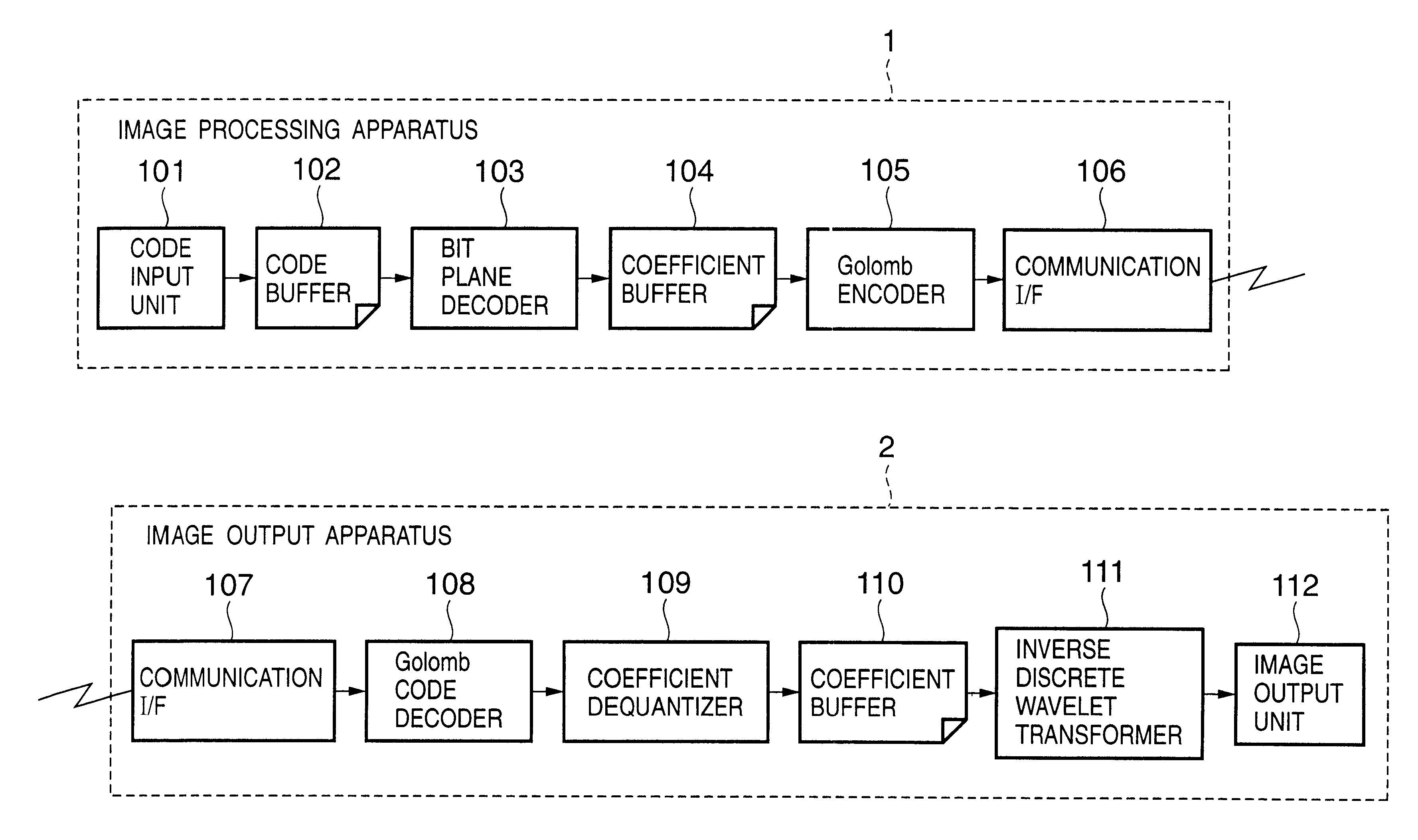
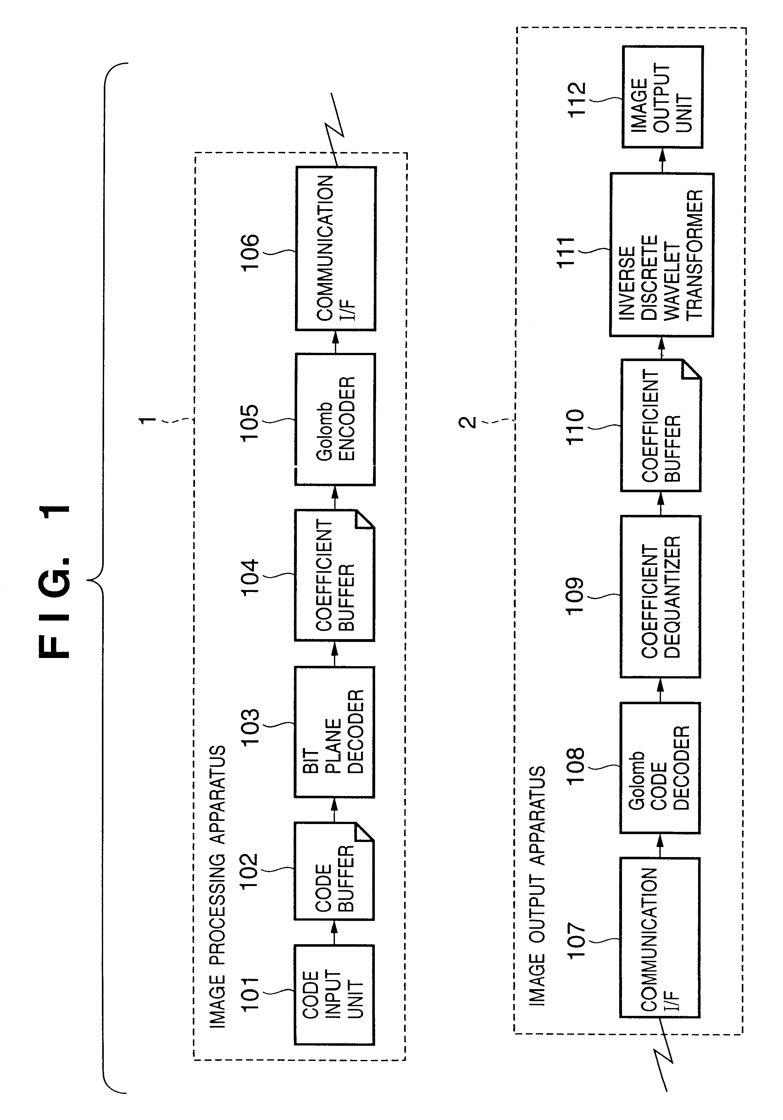
FIG. 1 is a block diagram showing the basic arrangement of an image processing system (image decoding apparatus) which includes an image processing apparatus and image output apparatus of this embodiment. Referring to FIG. 1, reference numeral 101 denotes a code input unit; 102, a code buffer; 103, a bit plane decoder; 104, a coefficient buffer; 105, a Golomb encoder; 106 and 107, communication interfaces; 108, a Golomb code decoder; 109, a coefficient dequantizer; 110, a coefficient buffer; 111, an inverse discrete wavelet transformer; and 112, an image output unit.

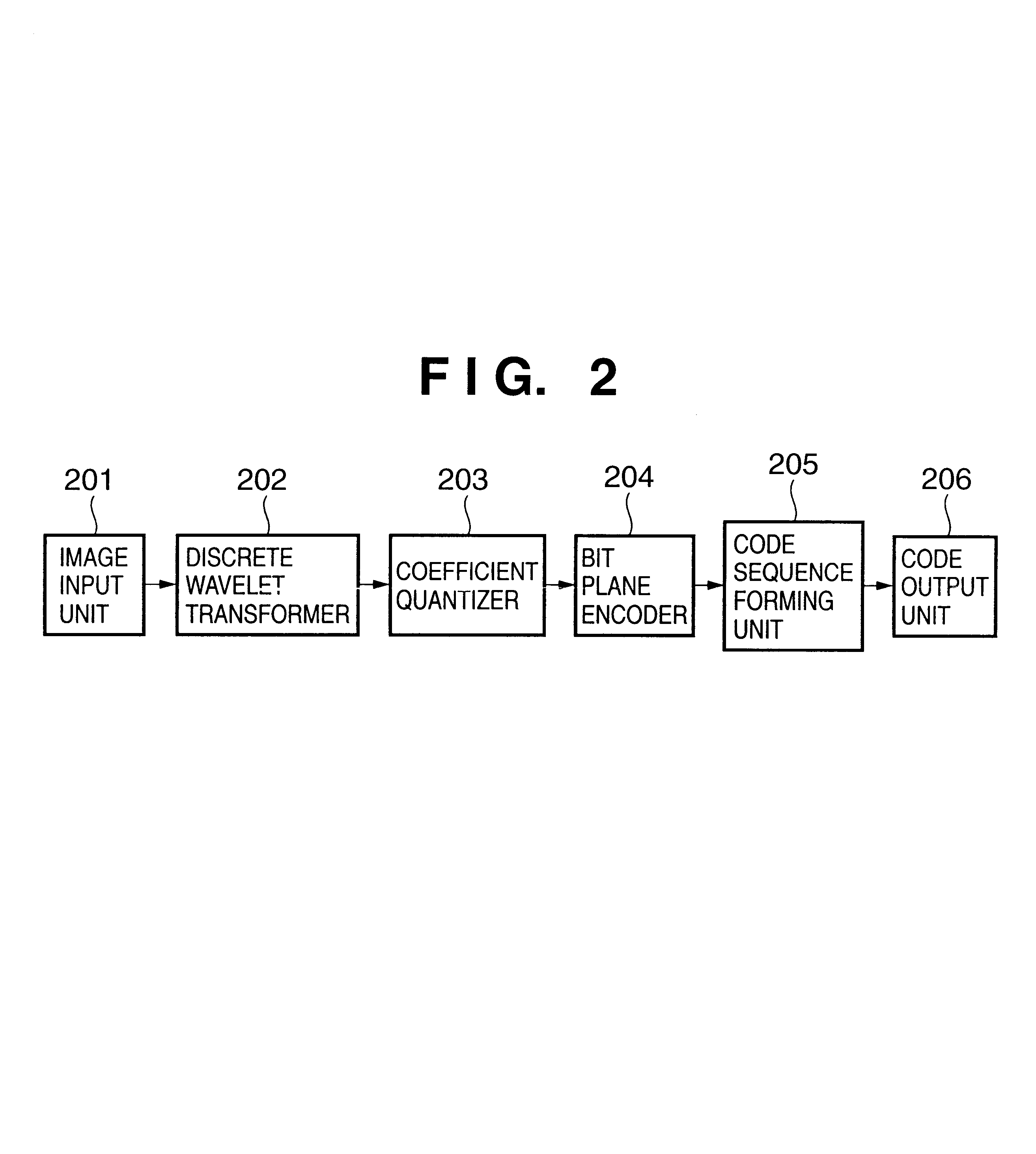
This embodiment uses monochrome image data in which the luminance value of one pixel is expressed by 8 bits. In the following description, encoded data scalably encoded by the image encoding apparatus with the arrangement shown in FIG. 2 is decoded, and a decoded image is output (the same applies to the following embodiments). However, the present invention is not limited to such specific data, and can ...

second embodiment

[Second Embodiment]

FIG. 10 is a block diagram of an image processing system according to the second embodiment. The same reference numerals in FIG. 10 denote common parts to those in the block diagram of FIG. 1 used in the first embodiment, and a description thereof will be omitted. Referring to FIG. 10, reference numeral 1001 denotes a rate controller; and 1002, a code order change unit.

The operations of the respective units in this embodiment will be described below with reference to FIG. 10. An image processing apparatus 1′ and image output apparatus 2′ of this embodiment are the same as those in the block diagram in FIG. 1, except that the rate controller 1001 is added to the image processing apparatus 1 in FIG. 1, and the code order change unit 1002 is added to the image output unit 2. Also, the operations from the code input unit 101 to the Golomb encoder 105 are the same as those in the image processing system of the first embodiment. In this embodiment, encoding parameter k ...

third embodiment

[Third Embodiment]

FIG. 16 is a block diagram showing an image processing system according to the third embodiment. The same reference numerals in FIG. 16 denote parts common to those in the block diagrams in FIGS. 1 and 10 used in the respective first and second embodiments, and a detailed description thereof will be omitted. Referring to FIG. 16, reference numeral 1601 denotes a decoding subband determination unit; and 1602, a bit plane decoder. As can be seen from FIG. 16, the system of this embodiment has substantially the same arrangement as that of the image processing system of the second embodiment, except that the decoding subband determination unit 1601 is added to the image processing apparatus 1′ of the image processing system of the second embodiment.

The process in the decoding subband determination unit 1601 as a difference from the second embodiment will be explained below. The decoding subband determination unit 1601 holds the maximum number XOmax of pixels in the hor...


PUM


Abstract

This invention has as its object to attain efficient encoding/decoding even when the processing time, memory, arithmetic cost, and the like of an apparatus are limited.
Encoded image data is input to an image processing apparatus (1) to obtain transform coefficients of subbands. The transform coefficients required to decode an image from its head position line by line are encoded by Golomb coding using one line of a subband as a unit to generate a code sequence, which is output to an image output apparatus (2). The image output apparatus (2) reconstructs an image by decoding the Golomb encoded data, dequantizing the coefficients, and computing the inverse discrete wavelet transforms of the coefficients, and outputs the reconstructed image.

Description

FIELD OF THE INVENTIONThe present invention relates to an image processing system for encoding and / or decoding an image, an image processing apparatus, an image input apparatus, an image output apparatus and method, and a storage medium.BACKGROUND OF THE INVENTIONIn recent years, as the technologies for image input apparatuses such as digital cameras, scanners, and the like have improved, the resolution of image data captured by such input apparatus is increasing. A low-resolution image requires a small image data volume and never disturbs coding, transfer, and storage processes. However, the image data volume becomes huge with increasing resolution, and a long transfer time is often required. Hence, the coding and storage processes require a large storage size.As a method of efficiently transferring and displaying such large-size image data, scalable transfer of image data has received a lot of attention. In this method, data are transferred in turn from an image having low image q...

Claims


Application Information

Patent Timeline
IPC IPC(8): G06T9/00
CPCG06T9/007
Inventor KAJIWARA, HIROSHISATO, MAKOTOKISHI, HIROKI
Owner CANON KK
Why Eureka
Try Eureka