Pneumatic brake booster with reduced noise levels

a technology of pneumatic brake and booster, which is applied in the direction of braking system, servomotor, instruments, etc., can solve the problems of circuit not operating, noise is annoying to the driver, noise to occur, etc., and achieve the effect of low sound volum

Inactive Publication Date: 2005-02-01
ROBERT BOSCH GMBH
View PDF4 Cites 2 Cited by
  • Summary
  • Abstract
  • Description
  • Claims
  • Application Information

AI Technical Summary

Benefits of technology

It is therefore an object of the present invention to offer a pneumatic brake booster with low sound volume.

Problems solved by technology

The operation of the ABS device is likely to cause vibration, this vibration being transmitted to the entirety of the hydraulic circuit and causing noise to occur.
This noise is annoying to the driver, on the one hand for his driving comfort and, on the other hand, because he may worry that his braking circuit is not operating correctly.
This vibration is therefore a source of noise, the booster being particularly sensitive to this vibration because of the small thickness of the sheet metal of which the outer wall of the booster is made.
In addition, vibration at the pedalbox gives the driver of the vehicle an unpleasant feeling.
However, this device is very expensive, difficult to implement, and requires very minute adjustments.

Method used


Image

  • Pneumatic brake booster with reduced noise levels
  • Pneumatic brake booster with reduced noise levels
  • Pneumatic brake booster with reduced noise levels

Examples


Embodiment Construction

The same references are used in all the figures to denote elements which have more or less the same function.

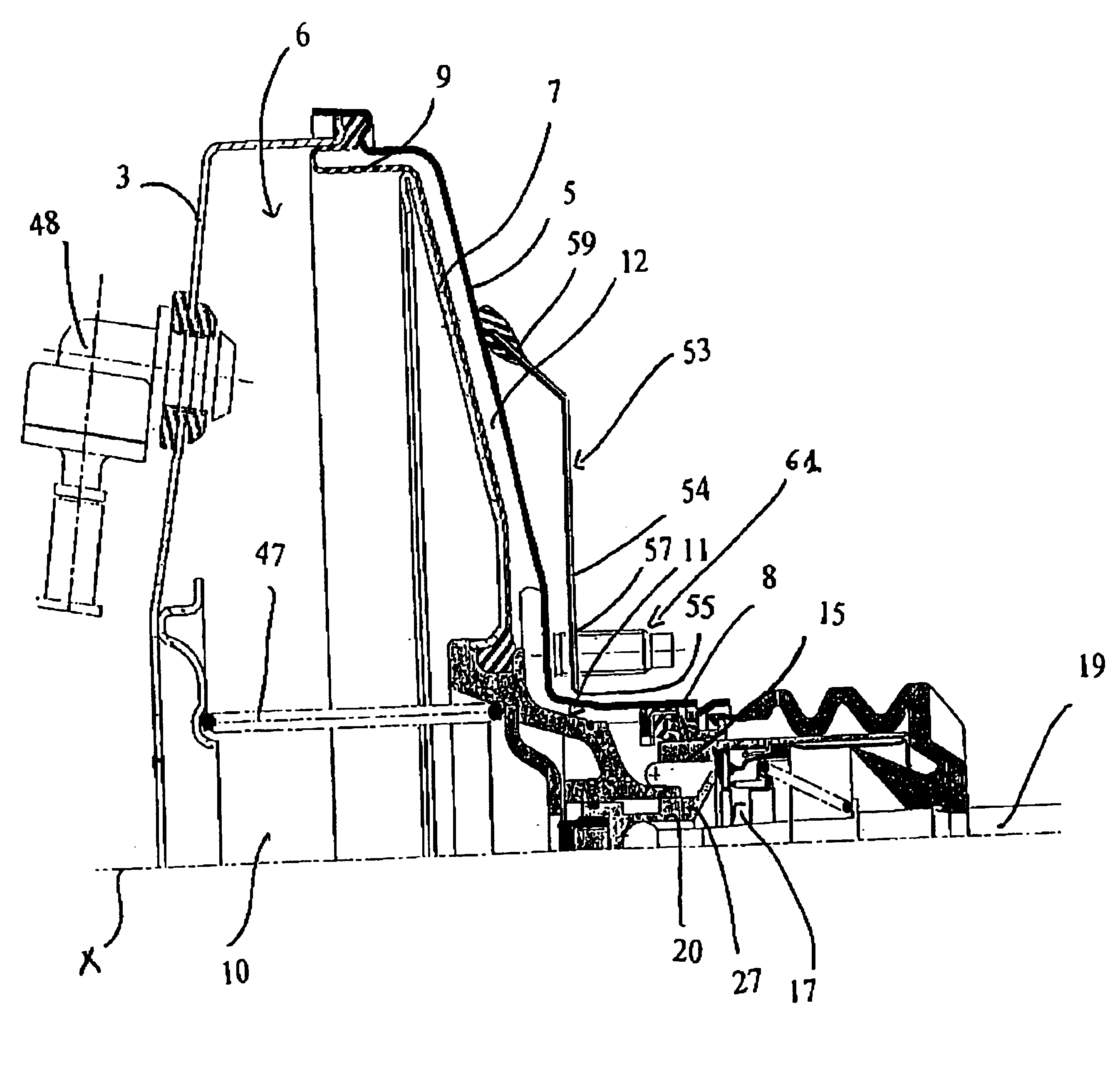
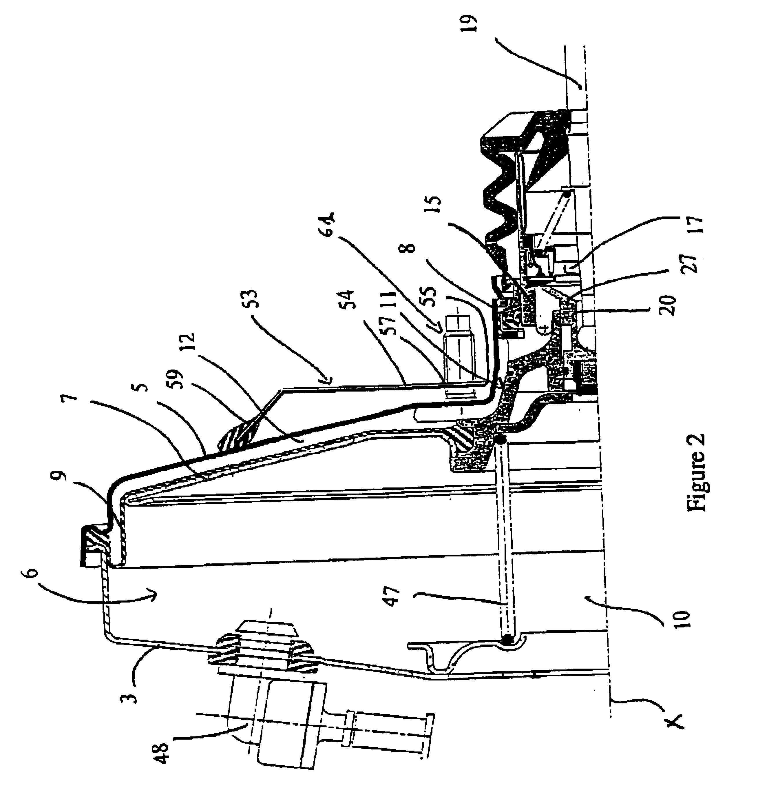
All of the elements described have a shape which has a symmetry of revolution about an axis X, the longitudinal axis of the booster.

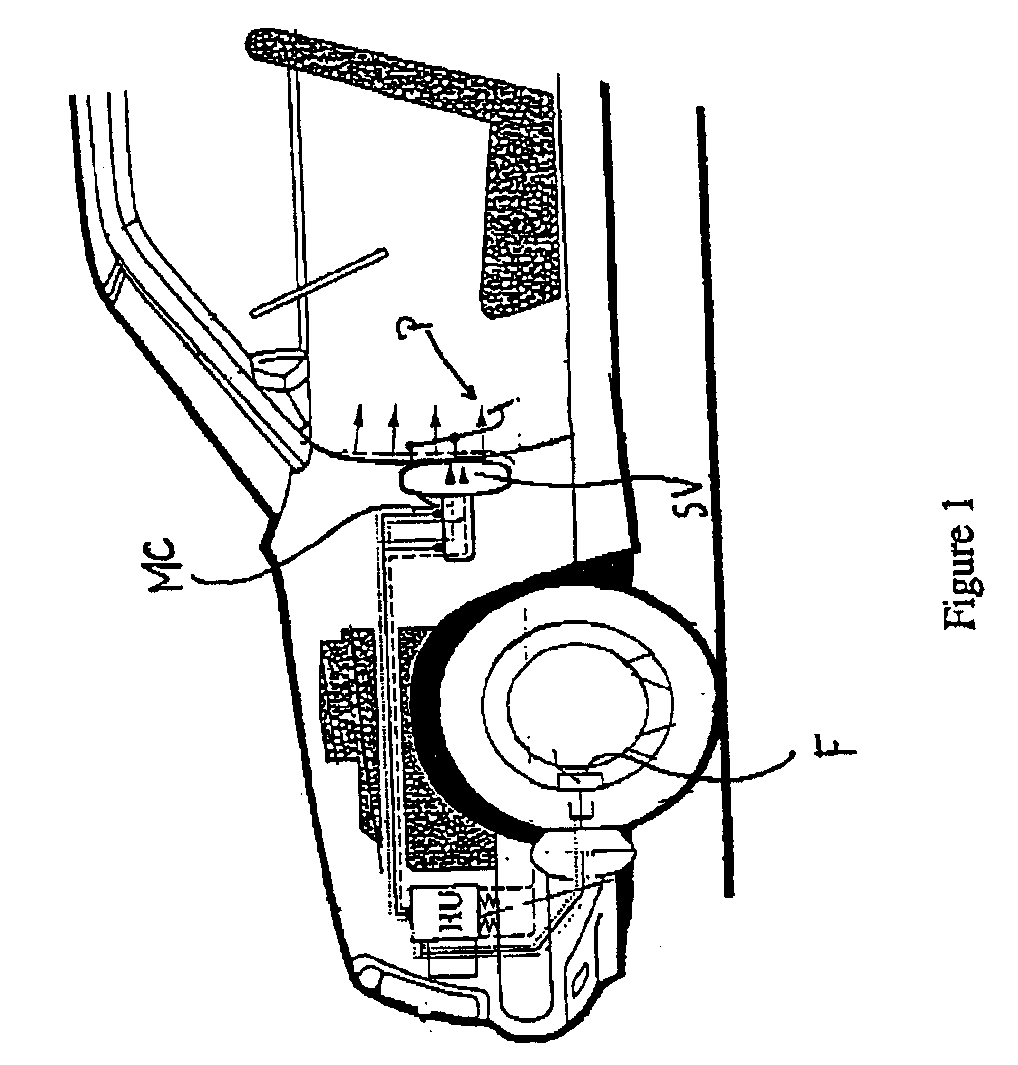
FIG. 1 is a schematic overview of a motor vehicle comprising a brake circuit equipped with a pedalbox P comprising at least one brake pedal actuating a control rod controlling a pneumatic brake booster of known type SV and a master cylinder MC connected to the brakes F arranged at the wheels. The braking circuit also comprises an ABS device HU arranged between the master cylinder and the wheels. The arrows depict the direction in which noise and vibration caused by the operation of the ABS device is transmitted.

FIG. 2 shows a pneumatic brake booster according to the present invention, of longitudinal axis X, comprising an envelope 1 formed of a first shell and a second shell 3, 5, crimped together around their exterior contour and defining an int...


PUM

PropertyMeasurementUnit
noiseaaaaaaaaaa
pressureaaaaaaaaaa
thicknessaaaaaaaaaa

Abstract

A pneumatic brake booster comprising an envelope formed of two shells (3, 5) defining an interior volume divided into two chambers by a skirt mounted so that it can slide with sealing. The skirt (7) is actuated by a pressure difference brought about by the operation of a three-way valve (17) arranged in a pneumatic piston arranged more or less in the central part of the skirt. The booster also comprising means (53) for reducing the noise, characterized in that the means (53) are bearing means comprising a layer of elastomer arranged between one of the shells (3, 5) and a rigid element.

Description

The present invention relates mainly to a pneumatic brake booster comprising means for reducing the noise.BACKGROUND OF THE INVENTIONBraking circuits of known type comprise a master cylinder boosted by a pneumatic brake booster, the braking circuit being actuated by a control rod connected to a brake pedal. Brake circuits also increasingly often comprise brake regulating devices so as to prevent the wheels from locking under emergency braking and thus improve the driver's control of the vehicle, these devices are known as ABS devices. ABS devices comprise an electronic computer gathering information from sensors arranged at the wheels of the vehicle so as to detect the locking of the wheels; ABS devices also comprise electrically operated valves, at least one pressure accumulator, a hydraulic pump, for example an electric pump for supplying pressurized brake fluid.When the computer of the ABS device detects that wheels are becoming locked, the computer initially releases the braking...

Claims


Application Information

Patent Timeline
Patent Type & Authority Patents(United States)
IPC IPC(8): B32B15/08B60T13/52B60T13/567G10K11/00G10K11/168B60T13/56
CPCB32B15/08G10K11/168B60T13/567B60T13/52
Inventor LORKIN, TIMOTHY
Owner ROBERT BOSCH GMBH
Why Eureka
Try Eureka