Floatable vessel lift

a floating device and lifting technology, applied in special-purpose vessels, valve operating means/releasing devices, couplings, etc., can solve the problems of inability to carry out hoist systems, inconvenient operation, and high installation and maintenance costs of hoist systems, so as to achieve the effect of water transpor

Inactive Publication Date: 2005-02-01
LIVING TRUST JORGE R SAINZ
View PDF6 Cites 9 Cited by
  • Summary
  • Abstract
  • Description
  • Claims
  • Application Information

AI Technical Summary

Benefits of technology

The present invention addresses some of the shortcomings of the prior art by providing a stable, portable and floatable vessel lift for dry vessel storage. The most sinkable vessels are motor boats from 20 feet to around 40 feet. The present invention utilizes rigid dynamically floatable pontoon chambers, which enable the boat lift to float evenly during use. Since the present invention floats, water transport is feasible. Furthermore, the present invention does not require the use of extensive cables or hoists during operation. The pontoon chambers used with a low pressure air supply and valve allow the user to vary the depth of the lift's submersion evenly. Once the user maneuvers the lift completely level under the subject vessel, the user increases the air volume within the pontoon chambers in order to cause the lift and the vessel to immerge out of the body of water evenly.

Problems solved by technology

Accordingly, the hoist systems normally lack any portability.
Hoist systems can also be costly to install and maintain and a user normally needs to constantly monitor the height of the boat if left hoisted to adjust to the changing water levels.
Davits are permanent and interfere with other uses of the dock.
Pontoons have the ability to automatically adjust to changes in the water level; however, pontoons may not provide the stability needed to support the vessel absent the use of extensive mechanical connections to the dock.
The pontoons may sink and rise with water level, however, most pontoons for boatlifting are expensive and fail to provide independent even stable support for the subject vessel.
The boatlift of Moody may provide a device to lift a vessel, however, the device requires a complex system of hoses and ropes for attachment to a dock.
The floatation device of Sackett may lack sufficient stability to function according to the user's needs.

Method used


Image

  • Floatable vessel lift
  • Floatable vessel lift
  • Floatable vessel lift

Examples


Embodiment Construction

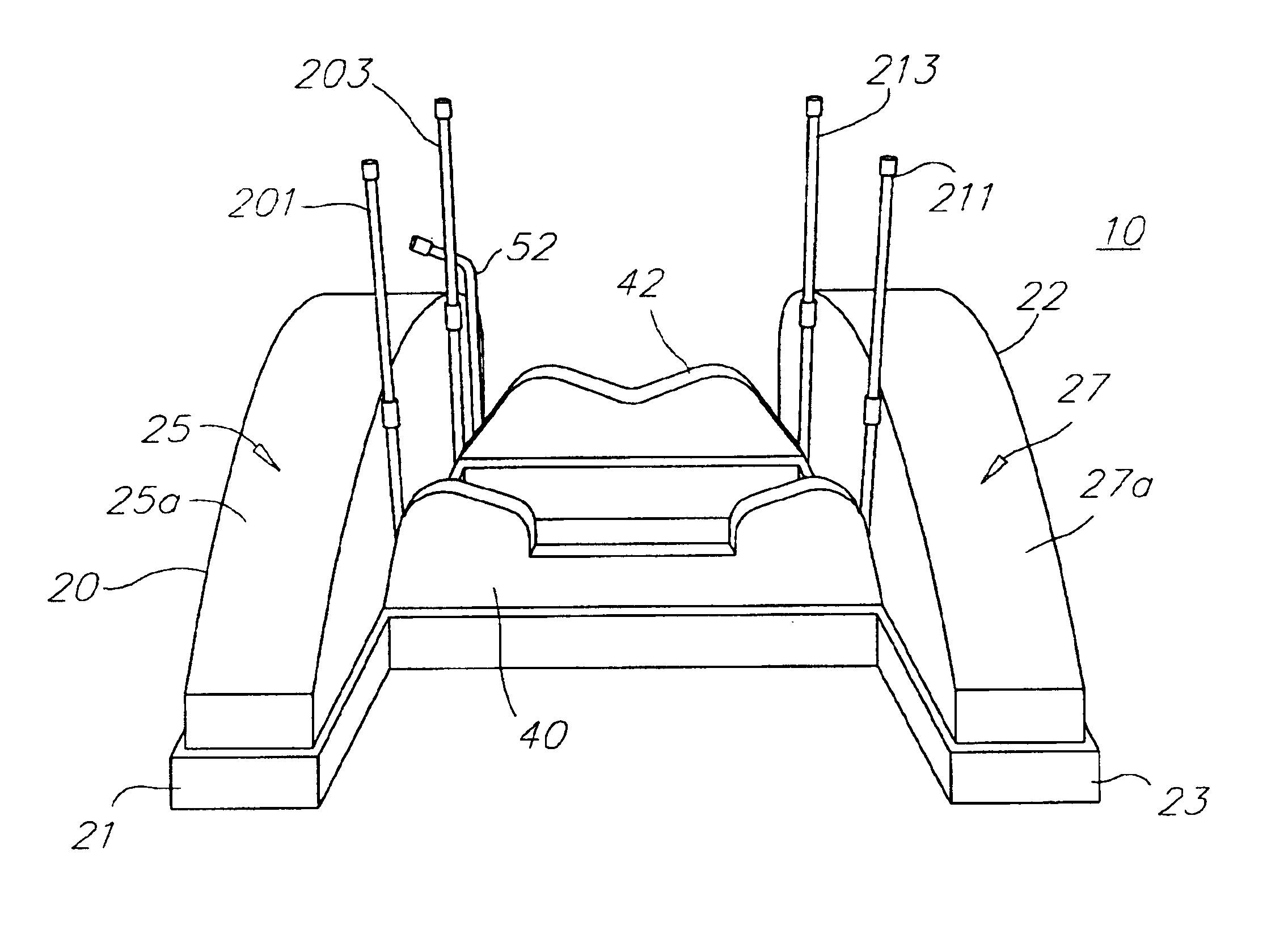
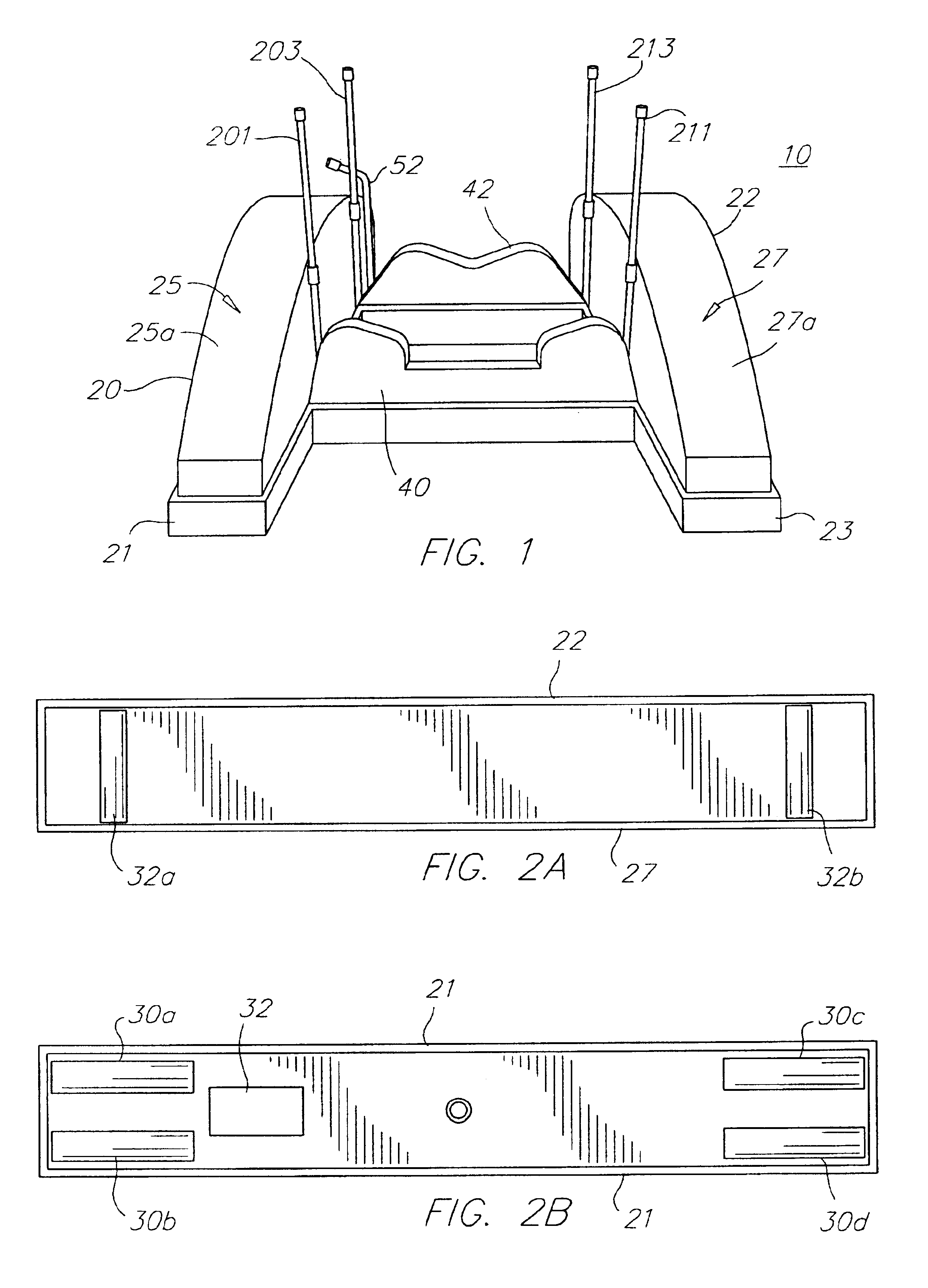
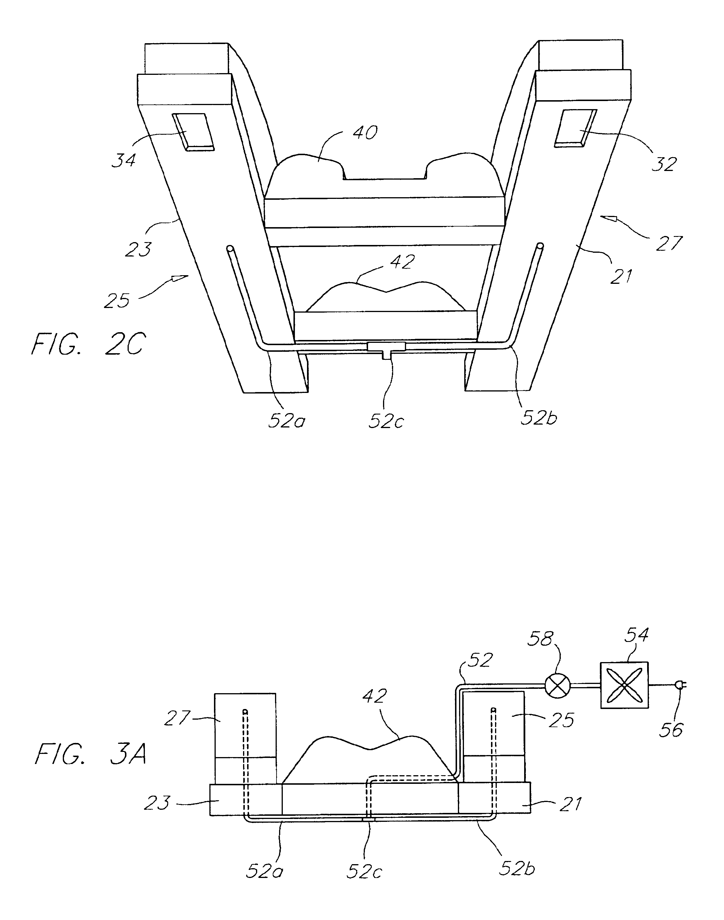
The present invention shown in FIG. 1 relates to a floatable vessel lift that provides a stable and portable device to lift a vessel evenly in a body of water. The floatable vessel lift 10 enables the user to lift a vessel evenly from the water for dry storage on at least two vessel support cross members 40 and 42 adjoined to floatable parallel pontoon chambers 25 and 27. The pontoon chambers 25 and 27 and vessel support members 40 and 42 are substantially submerged while the subject vessel (not shown) is positioned over the support cross members 40 and 42 in a longitudinally balanced and laterally symmetrically balanced position. In order to create the desired buoyancy or lift, the user inserts a single source of air into pipe 52 under pressure into the rigid air impermeable pontoon chambers causing the displacement of water within the pontoon chambers through apertures in the bottom of each pontoon chamber. As the volume of air increases in the pontoon chambers 25 and 27 and the v...


PUM


Abstract

The present invention relates to a floatable vessel lift comprising: at least two pontoon chambers, where each of the at least two pontoon chambers includes a top housing and a base. The pontoon's top housing has an arcuate longitudinal surface and the base side is substantially flat. Support members horizontally join the at least two pontoon chambers to support a vessel during the lifting process. A user varies the submersion of the vessel lift during use by using a single air infusion device that introduces an air flow into the at least two pontoon chambers simultaneously.

Description

BACKGROUND OF INVENTION1. Field of the InventionThe present invention relates to a floating device for lifting a vessel such as a motor boat typically sized from 19 feet to 39 feet from a body of water when the vessel is not in use, providing dry storage.2. Description of Related ArtMany docking techniques are available to boat users for boat removal and insertion into a body of water. One method involves the tying of the boat to a dock and implementing the use of a hoist lift system to remove and insert the subject boat. Usually, these hoist systems require the use of a davit, pulleys, cables and winches in various and normally complex configurations. The hoist lift systems usually include the use of a permanent dry dock in conjunction with the hoist system. Accordingly, the hoist systems normally lack any portability. Hoist systems can also be costly to install and maintain and a user normally needs to constantly monitor the height of the boat if left hoisted to adjust to the chan...

Claims


Application Information

Patent Timeline
Patent Type & Authority Patents(United States)
IPC IPC(8): B63C1/00B63C1/04B63C1/06
CPCB63C1/04B63C1/06Y10T403/12
Inventor SAINZ, JORGE R.
Owner LIVING TRUST JORGE R SAINZ
Why Eureka
Try Eureka