Check patentability & draft patents in minutes with Patsnap Eureka AI!

Temperature control apparatus

a technology of temperature control apparatus and control device, which is applied in the direction of light and heating apparatus, indirect heat exchanger, machine operation mode, etc., can solve the problems of poor maintainability, poor space efficiency, and inability to absorb thermal distortion in heat exchangers, so as to achieve the effect of easy replacemen

Inactive Publication Date: 2005-02-01
KOMATSU LTD
View PDF5 Cites 52 Cited by
  • Summary
  • Abstract
  • Description
  • Claims
  • Application Information

AI Technical Summary

Benefits of technology

[0009]In view of the discussion thus far described, therefore, the present invention has an object to provide a temperature control apparatus having the structure which is easy in the replacement of a heat exchange unit to enhance the maintainability and the space efficiency and which can absorb the distortion of a heat exchanger due to the thermal expansion or shrinkage.
[0013]According to the invention, the relay block has the passage between the passage block and the connecting pipe of the heat exchange unit, and the length of the connecting pipe is substantially equal to or slightly shorter than the spacing between the heat exchanger and the passage block. Where the heat exchange unit is troubled, therefore, the troubled heat exchange unit can be easily replaced by a new one by removing the relay block connected to the troubled heat exchange unit from the passage block. On the other hand, the connecting pipe of the heat exchange unit is connected to the passage of the relay block by using the sealing means that mentioned above so that the distortion of the heat exchanger due to the thermal expansion or shrinkage can be absorbed.

Problems solved by technology

In this temperature control apparatus of the prior art, however, a space is needed for turning the nuts 34 and 35 so that there is a problem that the space efficiency is poor.
Where the heat exchange unit 30 is arranged in a narrow space, on the other hand, the nuts 34 and 35 are hard to be turned thereby raise another problem that the maintainability is poor.
Moreover, the heat exchanger is fixed at its two ends to raise another problem that the thermal distortion in the heat exchanger cannot be absorbed.
With this construction, however, the passage block and the heat exchange unit have to be precisely machined and that leads to rise in cost.
With this construction, however, it is impossible to absorb the distortion of the heat exchanger, as caused by the thermal expansion or shrinkage.

Method used


Image

  • Temperature control apparatus
  • Temperature control apparatus
  • Temperature control apparatus

Examples


Embodiment Construction

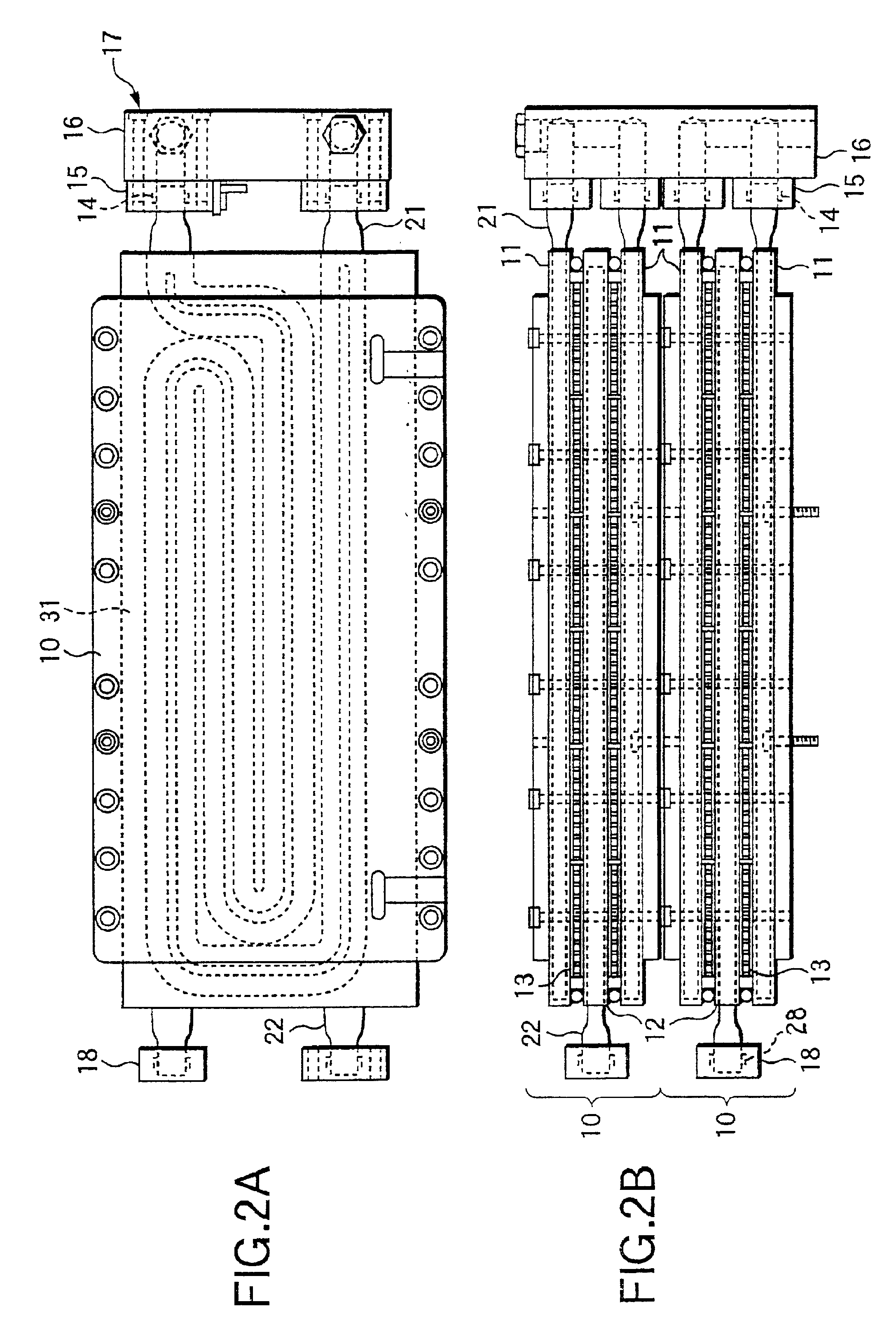
ttom right-hand portion of the heat-exchange unit shown in FIG. 2B;

[0017]FIG. 2D is a partial cross sectional view of the bottom left-hand portion of the heat-exchange unit shown in FIG. 2B taken along line 2D—2D of FIG. 1; and

[0018]FIG. 3 is a top plan view showing a portion of the temperature control apparatus of the prior art.

DESCRIPTION OF THE PREFERRED EMBODIMENT

[0019]Here will be described an embodiment of the invention with reference to the accompanying drawings.

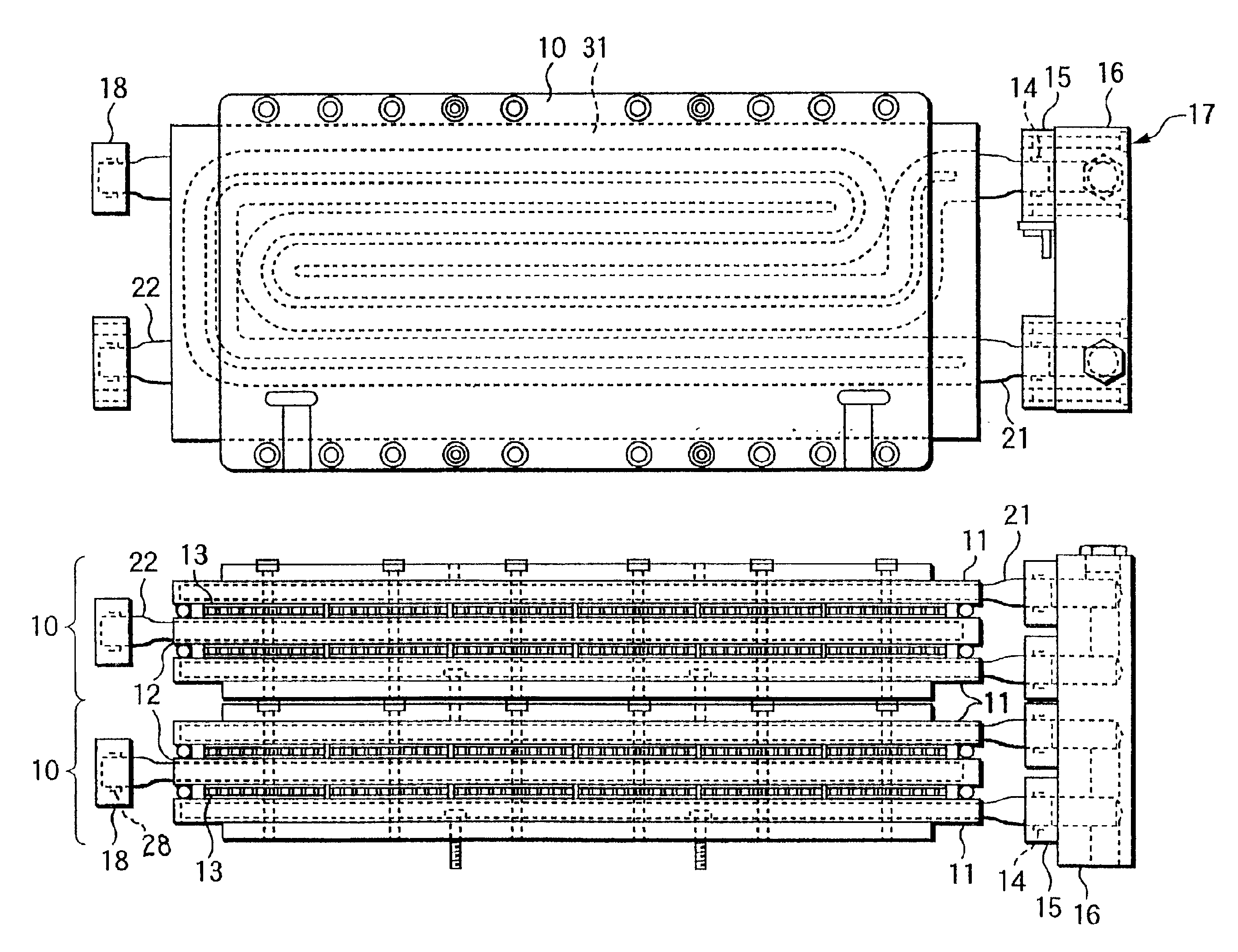
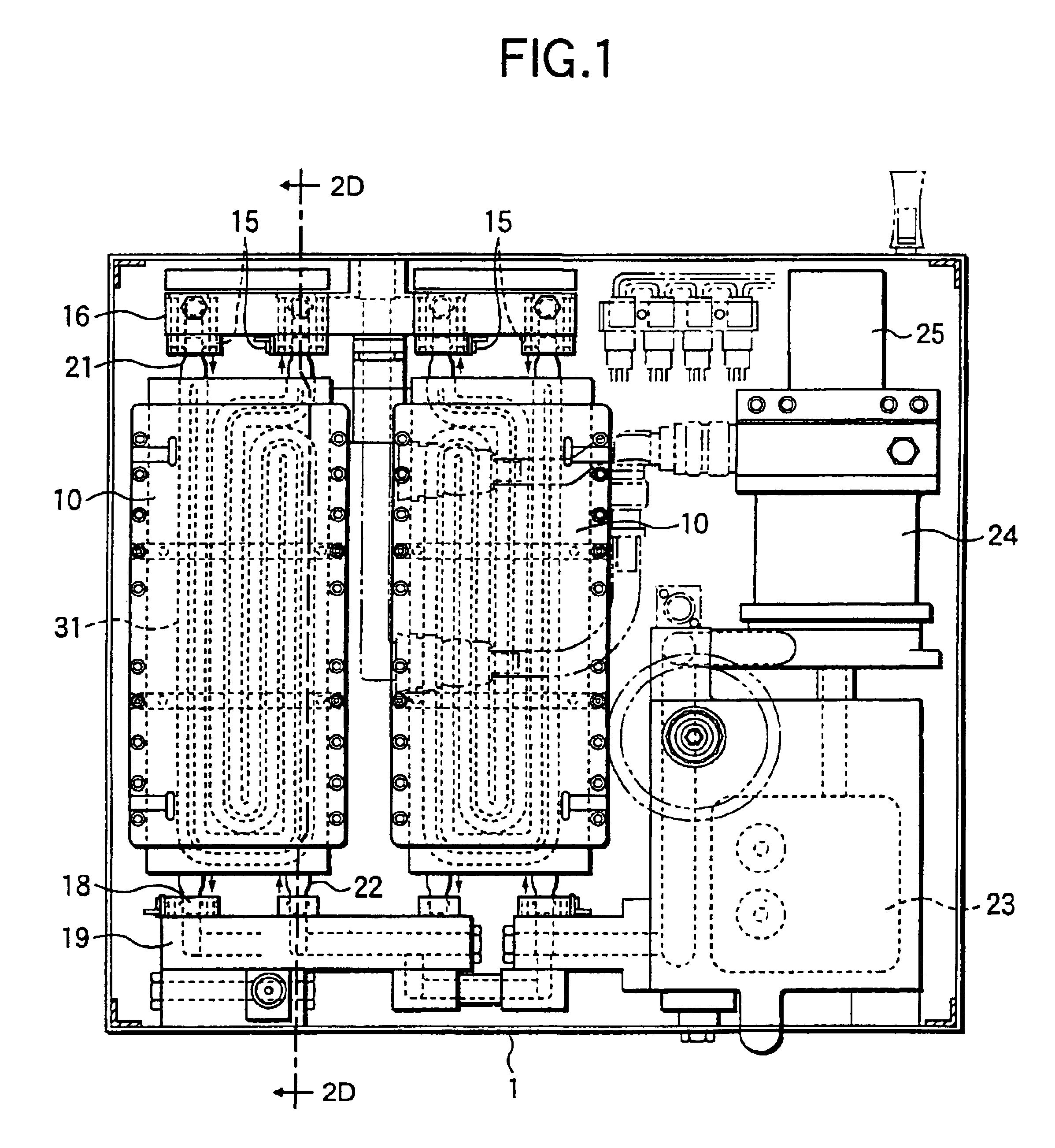
[0020]FIG. 1 is a top plan view showing a temperature control apparatus according to one embodiment of the invention. In this embodiment, the invention is applied to a temperature control apparatus for cooling an etching apparatus. As shown in FIG. 1, this temperature control apparatus is provided with heat exchange units 10 which are arrayed in two columns in the horizontal direction. The heat exchange unit 10 is so removably attached to a casing 1 of the temperature control apparatus that it can be replaced, when tr...


PUM


Abstract

A temperature control apparatus where it is easy to replace a heat exchange unit to enhance the maintainability and the space efficiency and which can absorb the thermal expansion / shrinkage of a heat exchanger is provided. The temperature control apparatus has a heat exchanger 11 with a passage 31 for passing a fluid; a connecting pipe 21 connected to the passage of the heat exchanger; a passage block 16 with a passage for passing the fluid to the heat exchanger; a relay block 15 for forming a passage between the passage of the passage block and the connecting pipe; and sealing means 14 for connecting the connecting pipe movably to the passage of the relay block. In the temperature control apparatus, the length of the connecting pipe 21 is made substantially equal to or slightly shorter than the spacing between the heat exchanger 11 and the passage block 16.

Description

BACKGROUND OF THE INVENTION[0002]1. Field of the Invention[0003]The present invention relates to a temperature control apparatus for controlling the temperature of another apparatus and, more particularly, to a temperature control apparatus for cooling a semiconductor manufacturing apparatus such as an etching apparatus by exchanging the heat between a heat exchanger for passing a liquid (or a temperature controlling fluid) fed from the outside and a heat exchanger for passing a circulating liquid (or a temperature controlled fluid) and by using this circulating liquid.[0004]2. Related Art[0005]The temperature control apparatus of the prior art, as used for cooling a semiconductor manufacturing apparatus such as an etching apparatus, is provided with a heat exchanger unit 30, as shown in FIG. 3. This heat exchanger unit 30 includes: a cooling water heat exchanger (or a temperature controlling heat exchanger) having a cooling water passage 31 formed for passing the cooling water fed ...

Claims


Application Information

Patent Timeline
IPC IPC(8): F28F9/26H01L21/00F25B21/02F25B41/00F28D9/00
CPCF28F9/26H01L21/67109H01L21/67017F25B41/00
Inventor SEKI, MASANOBUTOKUDA, MINEO
Owner KOMATSU LTD
Features
  • R&D
  • Intellectual Property
  • Life Sciences
  • Materials
  • Tech Scout
  • Unparalleled Data Quality
  • Higher Quality Content
  • 60% Fewer Hallucinations
Learn More