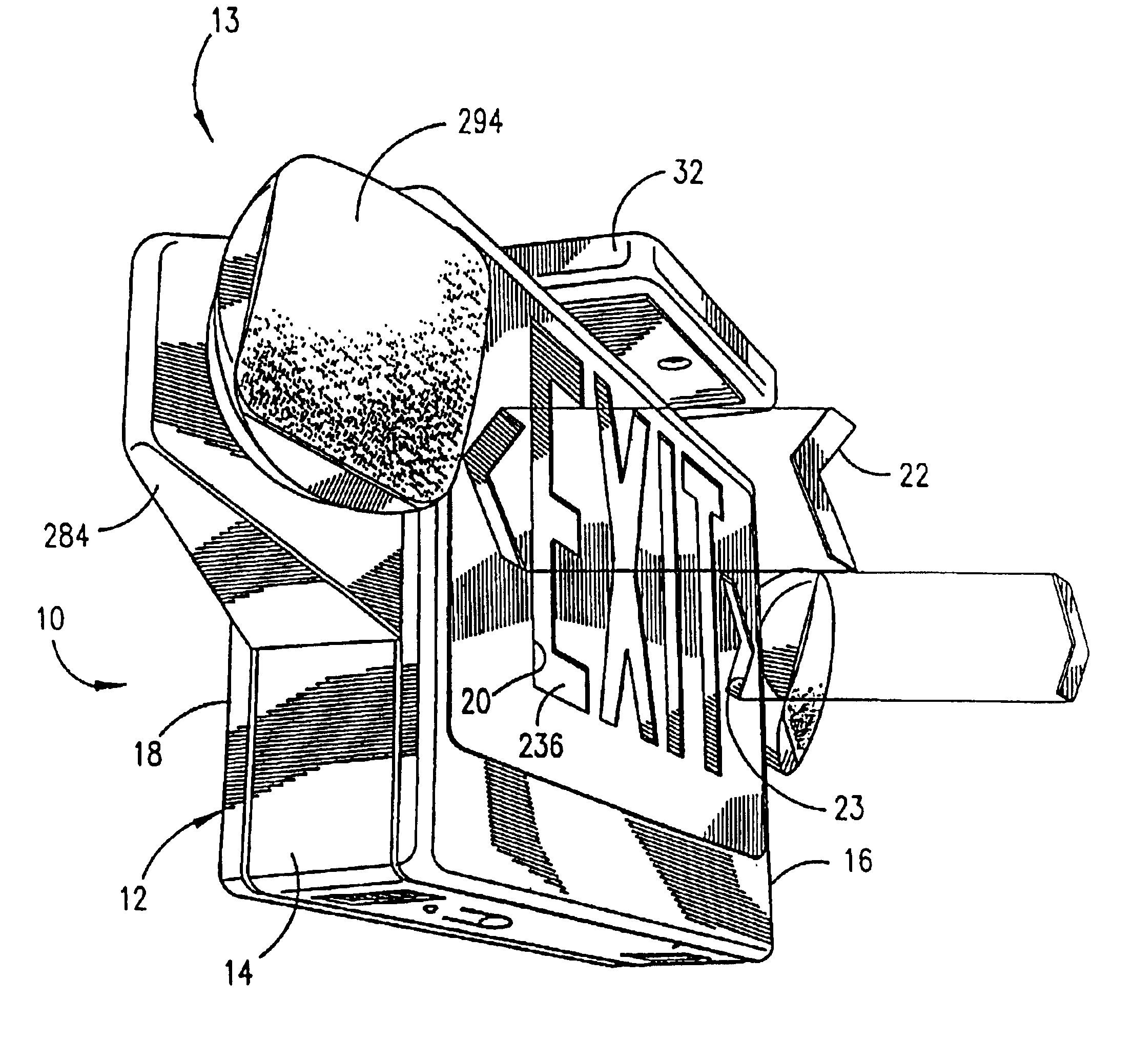
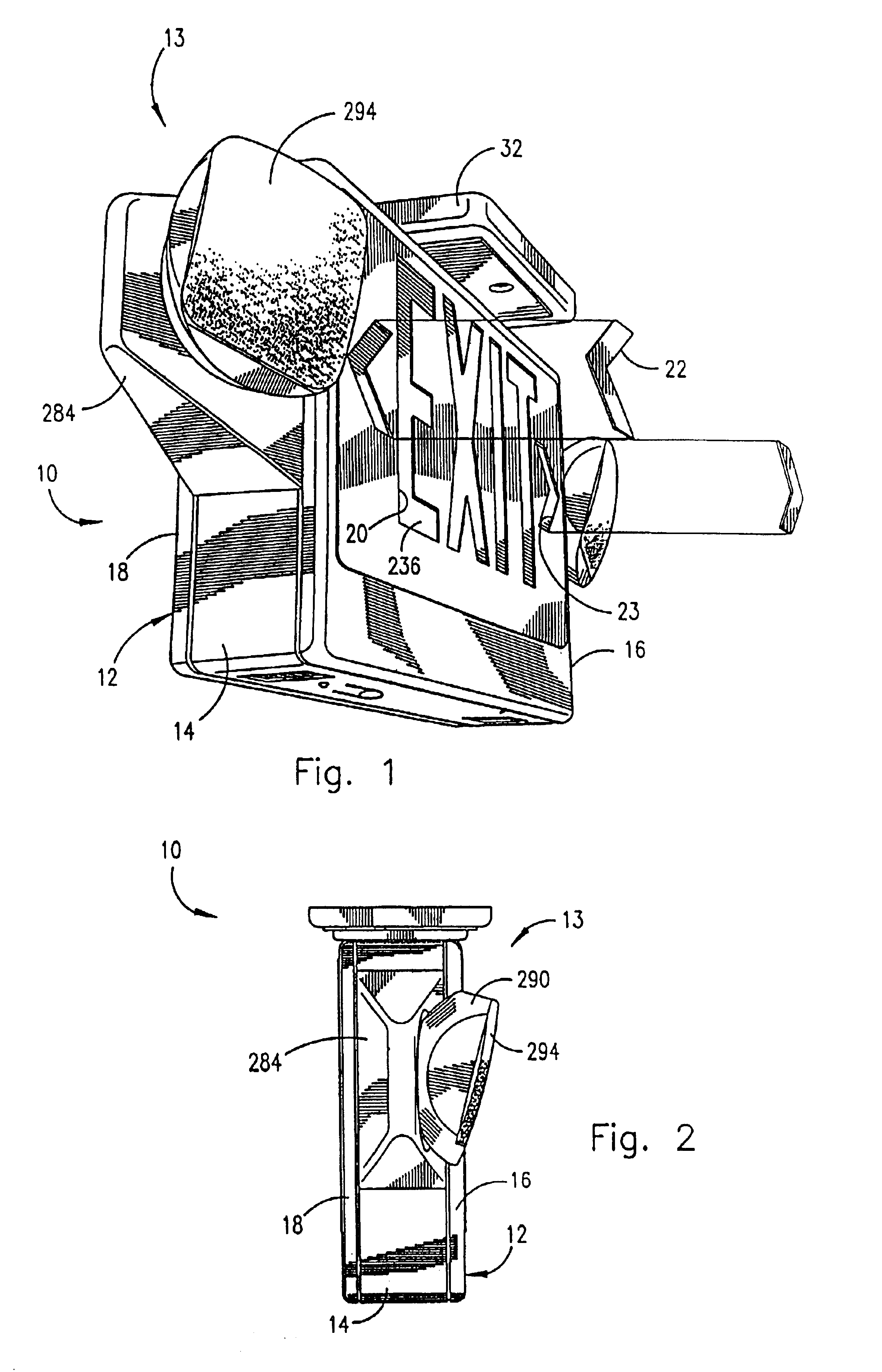
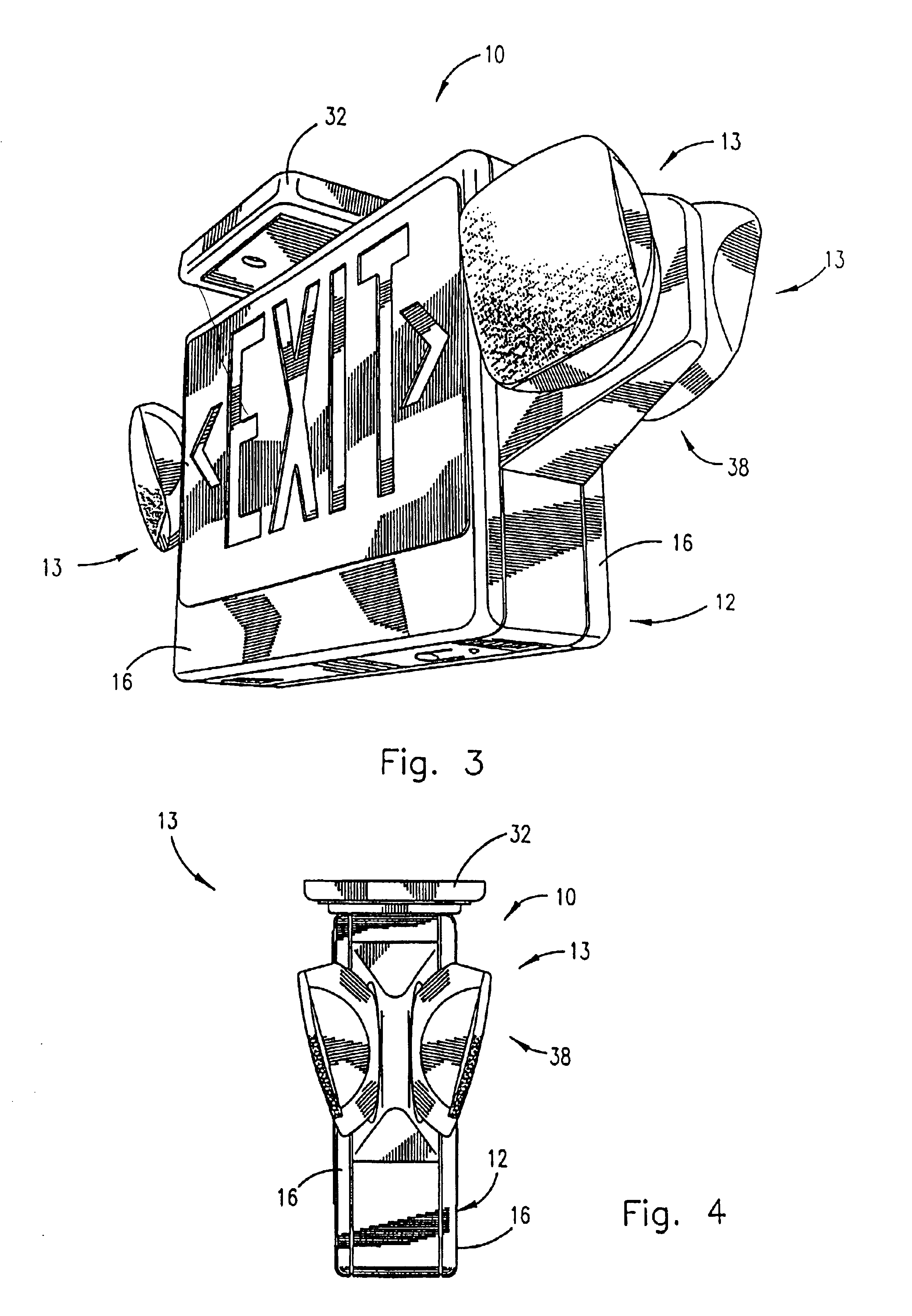
The invention provides an emergency lighting fixture which combines the functions of an illuminated sign, particularly an exit sign, with an emergency lighting unit, the structural combination being integrated into a single housing which internally contains those structural elements necessary to produce the functions of the feature and which carries emergency lamping externally of the housing at multiple locations thereby providing extraordinary flexibility in use. The present combination of an exit sign and an emergency lighting unit or “exit / unit combo” is preferably formed of a polymeric material such as
polycarbonate / ABS, thereby allowing molding of a fixture housing with most of the structural elements necessary to produce the functions of the fixture being integrally formed with the housing, these molded structural elements and other structure contained within the housing being located in the housing in a manner whereby the elements combine to produce synergistic effects in addition to the primary functions of the structural elements, the fixture being totally integrated as to
structure and function as well as being substantially integral in construction. Formation of the fixture essentially from moldable material further allows integral formation of snap-fitting structural elements which not only provide easy snap fitting of facing plates to the housing to form the primary structural portion of the combo per se but also the integral formation of snap-fitting structure with
bulb holders, battery mounting elements and option board storage elements inter; alia.
Assembly of the fixture is therefore facilitated at least in part due to the reduced number of individual parts occasioned by the integral nature of the housing inter alia.
The housing of the present exit / unit combo fixture is configured to support battery weights inter alia which are typically greater than those battery weights encountered in conventional exit signs due to the need to operate exit lighting, unit lighting and even
remote unit lighting with a single battery disposed within the housing. In order to accommodate greater battery weight and the weight of the fixture itself, the battery is centered with the housing disposed at a lower portion thereof, battery location couples with a central, vertical structural beam known as a “ladder” allows support of the battery inter alia in tension rather than in a cantilevered arrangement as has been previously employed in exit signs and the like. The structural features such as the ladder integrated with location of major weighting such as the weight of the battery actually allows use of a material such as plastic for formation of the fixture, the self-support provided by the structure itself preventing warping and bowing of the plastic exit / unit combo fixture over time such as would occur with a fixture having the weight of the exit / unit combo fixture if not provided with the integrated structural relationships of the invention. The dimensional stability of the present exit / unit combo fixture occurs due to the structural features of the fixture which maintain substantial portions of the fixture weight in tension.
The exit / unit combo fixture of the invention provides “unit” emergency lighting by the disposition of one or more emergency lamps mountable at different locations on the periphery of the fixture housing to accommodate differing lighting situations. The lamps are mounted by lamp holders fitted with swiveling concentric spherical structural elements which allow movement of the lamps with a degree of freedom not previously possible, the structure of the concentric spherical elements additionally yielding a compact profile which is not only attractive in appearance but functional due to the
volumetric efficiency thus provided. The lamp holders of the invention are formed with torsion snap elements which fit into slots formed in
peripheral edges of the housing, the slots receiving the snap elements of the lamp holders to positively
mount the lamp holders in desired locations on the fixture. The particular snap element / slot arrangement of the invention allows rapid and ready mounting and dismounting of the lamp holders to and from the fixture housing with positive locking of the lamp holders to the housing once assembled. The lamp holders of the invention can be removed from the present fixture and mounted to remote slave mounting stations driven by the fixture with the snap elements of the lamp holder fitting into arranged slots of the slave
station. Further, the lamp holder can be mounted to a
station separate from the fixture with battery or other operation, the lamp holder being mounted to the
station through use of the snap elements of the lamp holder in cooperation with slots formed in the station.
Various other features of the invention include structure for minimizing the “shadow” of the battery appearing through face plates of the exit / unit combo fixture; registration structure for mounting of a
diffusion panel in a face plate of the fixtures; routing of wiring in association with the ladder support and in front of the battery with the use of slack in the wiring and structure for compartmentalization of electrical components within the interior of the fixture housing including snap-mounting of a
capacitor inter alia. Many of the inventive features disclosed herein are useful in fixtures other than exit / unit combo fixtures and are disclosed for use in that variety of fixtures for which these features find utility. Use of these features is thus not limited to use in an exit / unit combo fixture.
It is a further object of the invention to provide an integral exit / unit combo fixture substantially moldable of a polymeric material with structural support features providing dimensional stability to the fixture thereby minimizing warping and bowing of the fixture over time in
spite of substantial weight occasioned by the use of heavy batteries as well as the weight of the fixture itself, the fixture including internal support elements which
mount battery weight as well as the weight of the fixture per se substantially in tension.
It is a still further object of the invention to provide an integral exit / unit combo fixture having unit lighting provided by lamps mounted on exterior portions of the fixture by lamp holders mounted to the fixture by tension snap elements, each lamp being mounted by a swiveling double concentric structure which allows an extraordinary
range of movement of the lamp and which allows formation of the unit lighting structure with a compact profile, the fixture requiring a reduced volume and vertical height for mounting of the fixture, the fixture being also mountable with the back of the fixture directly against a flat surface such as a wall.


