Excessive voltage protector for a variable frequency generating system

a voltage protector and variable frequency technology, applied in the field of systems, can solve problems such as the voltage at the por rising to undesirable levels

Inactive Publication Date: 2005-02-01
HAMILTON SUNDSTRAND CORP
View PDF59 Cites 49 Cited by
  • Summary
  • Abstract
  • Description
  • Claims
  • Application Information

AI Technical Summary

Benefits of technology

The present invention is directed to a variable frequency generating system that detects single point failures in a generator control unit and prevents excessive voltages at the point of regulation (POR) in a system. The generator control unit controls the operation of an exciter drive circuit, which in turn controls the voltage level at the POR. In one embodiment, the generator control unit is designed to detect at least one failure type, such as a loss of three-phase voltage sensing capability, switch failure in the exciter drive circuit, and / or exciter current loop failure.

Problems solved by technology

If a failure occurs, the generator control unit stops operation of the exciter drive circuit, preventing the voltage at the POR from rising to undesirable levels.

Method used


Image

  • Excessive voltage protector for a variable frequency generating system
  • Excessive voltage protector for a variable frequency generating system
  • Excessive voltage protector for a variable frequency generating system

Examples


Embodiment Construction

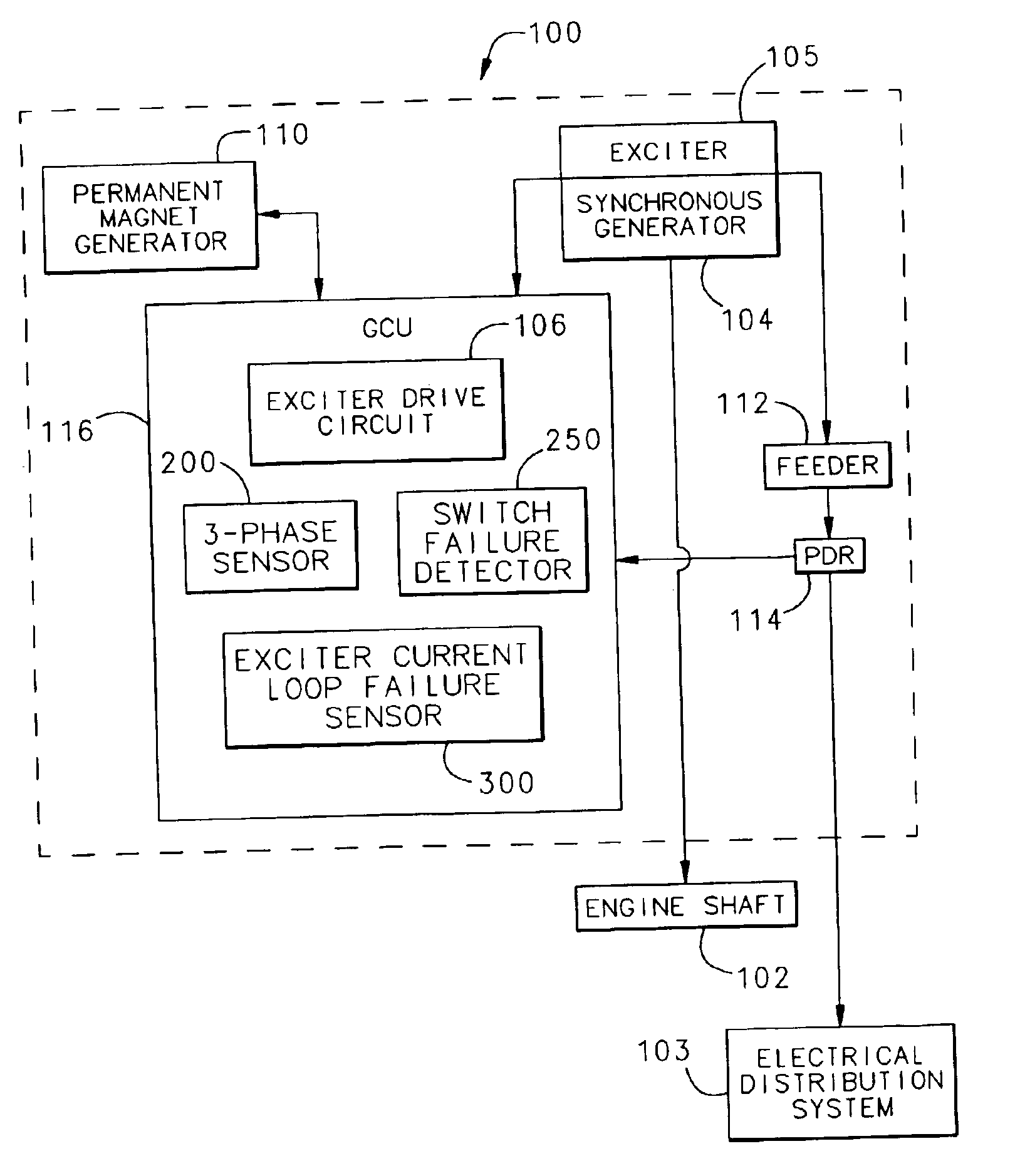
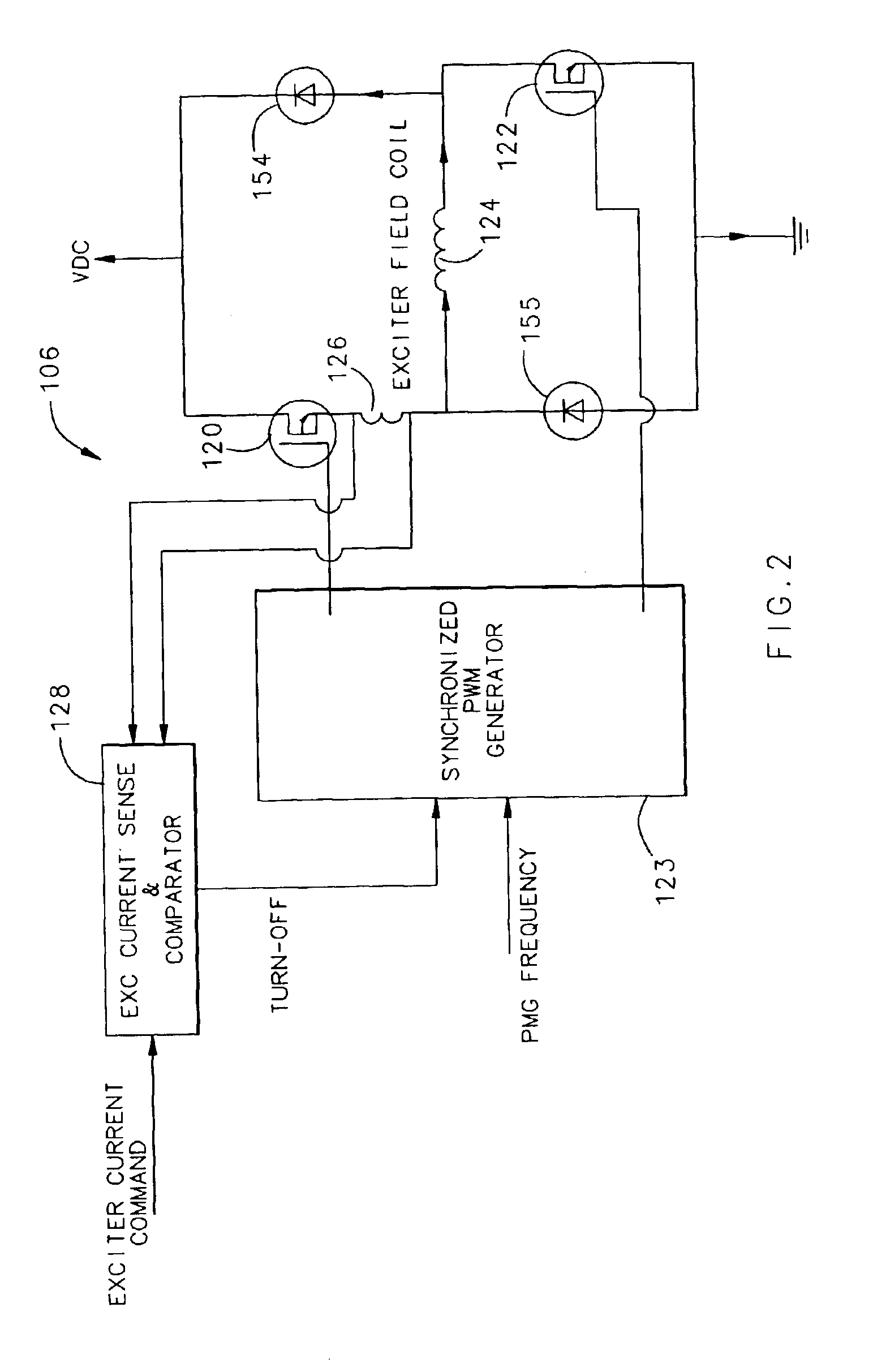
FIG. 1 illustrates a basic aircraft power generating system in which the invention operates. The system generally is a variable frequency generating system 100 that is coupled to a prime mover shaft, such as an aircraft engine shaft 102. The system 100 includes an electrical distribution system 103, a synchronous generator 104, an exciter 105, an exciter drive circuit 106, and a permanent magnet generator 110. In one embodiment, the exciter 105 is a synchronous machine with a stationary field and a rotating armature. As is known in the art, an engine (not shown) provides mechanical power to the synchronous generator 104 through the shaft 102; the generator 104 then converts the mechanical power into electrical power and provides the electrical power to electrical loads through a distribution system (not shown).

As shown in FIG. 1, the exciter 105 and synchronous generator 104 are incorporated into a single device. A feeder 112 carries current from the synchronous generator 104 to the...


PUM


Abstract

An excessive voltage protection system for a variable frequency generating system detects single point failures in a generator control unit and prevents excessive voltages at a point of regulation (POR) in the system. The generator control unit is designed to detect failures, such as a loss of three-phase sensing capability, switch failure in the exciter drive circuit, and/or exciter current loop failure. If a failure occurs, the generator control unit stops operation of the exciter drive circuit, preventing the voltage at the POR from rising to undesirable levels.

Description

TECHNICAL FIELDThe present invention relates to systems that protect a circuit from high voltages, and more particularly to a protector that prevents excessive voltage buildup caused by a failure within a variable frequency generating system.BACKGROUND OF THE INVENTIONTypically, commercial aircraft normally have a constant frequency generating system where the frequency of the voltage and current being sent through the feeder to the distribution system, and ultimately to the load, is kept constant within a narrow range, around 400 Hz. More recently, however, variable frequency systems are being incorporated into aircraft. These systems allow the frequency to range from as low as 375 Hz to 810 Hz while still maintaining the voltage magnitude at a constant level.The variable frequency generator has a synchronous generator that generates an output voltage that is regulated by an exciter field current. The output voltage of the synchronous generator at the point of regulation (POR) is r...

Claims


Application Information

Patent Timeline
Patent Type & Authority Patents(United States)
IPC IPC(8): H02H7/06
CPCH02H7/065
Inventor MADDALI, VIJAY
Owner HAMILTON SUNDSTRAND CORP
Why Eureka
Try Eureka