System for determining position and velocity of targets from signals scattered by the targets

a target position and target technology, applied in the field of system for determining the position and velocity of targets from signals scattered by targets, can solve the problems of insufficient four measurement geometries and the simultaneous presence of several targets, and achieve the effect of improving the situation and being easy to transpor

Inactive Publication Date: 2005-02-01
TOTALFORSVARETAB FORSKNINGSINSTITUT FOI
View PDF14 Cites 30 Cited by
  • Summary
  • Abstract
  • Description
  • Claims
  • Application Information

AI Technical Summary

Benefits of technology

is to improve this situation. The improvement consists partly in that the surveillance function is distributed over a large number of dispersed but relatively simple radar stations, where some can be lost without the position picture being impaired in a crucial manner. As well, single radar stations are small and easily transported and can be put in place on short notice without comprehensive ground installations or other preparations and therefore cannot be detected in advance.

Problems solved by technology

A special problem is then how to handle simultaneous presence of several targets.
In this case four measurement geometries are not sufficient for a unique determination of target state.

Method used


Image

  • System for determining position and velocity of targets from signals scattered by the targets
  • System for determining position and velocity of targets from signals scattered by the targets
  • System for determining position and velocity of targets from signals scattered by the targets

Examples


Embodiment Construction

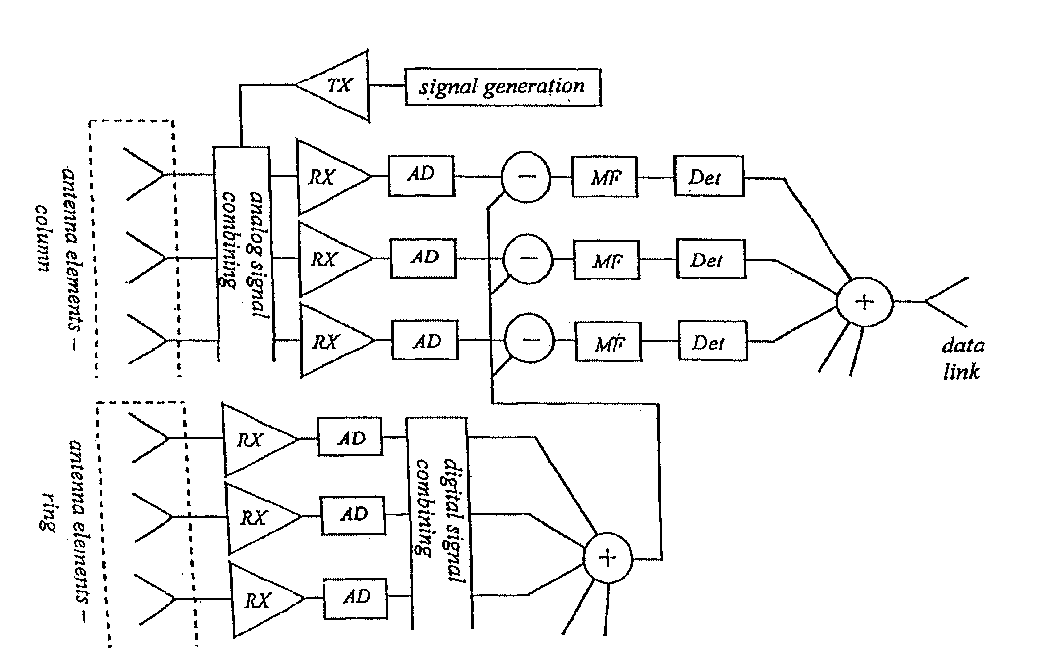
The system basically consists of a number of transmitters and receivers dispersed to known points in a position space, as well as analysis equipment. The system can, as stated, work with electromagnetic or acoustic signals. A conventional radar is mono-static, which means that the transmitter and receiver pair is located together. If they are spatially separated, however, the equipment is called bi-static. In the system it is expected that measurements can be made bi-statically and as well mono-statically. In the following a pair of a receiver RCVR and a transmitter XR, regardless of whether the measurement is bi-static or mono-static, is called a measurement facility.

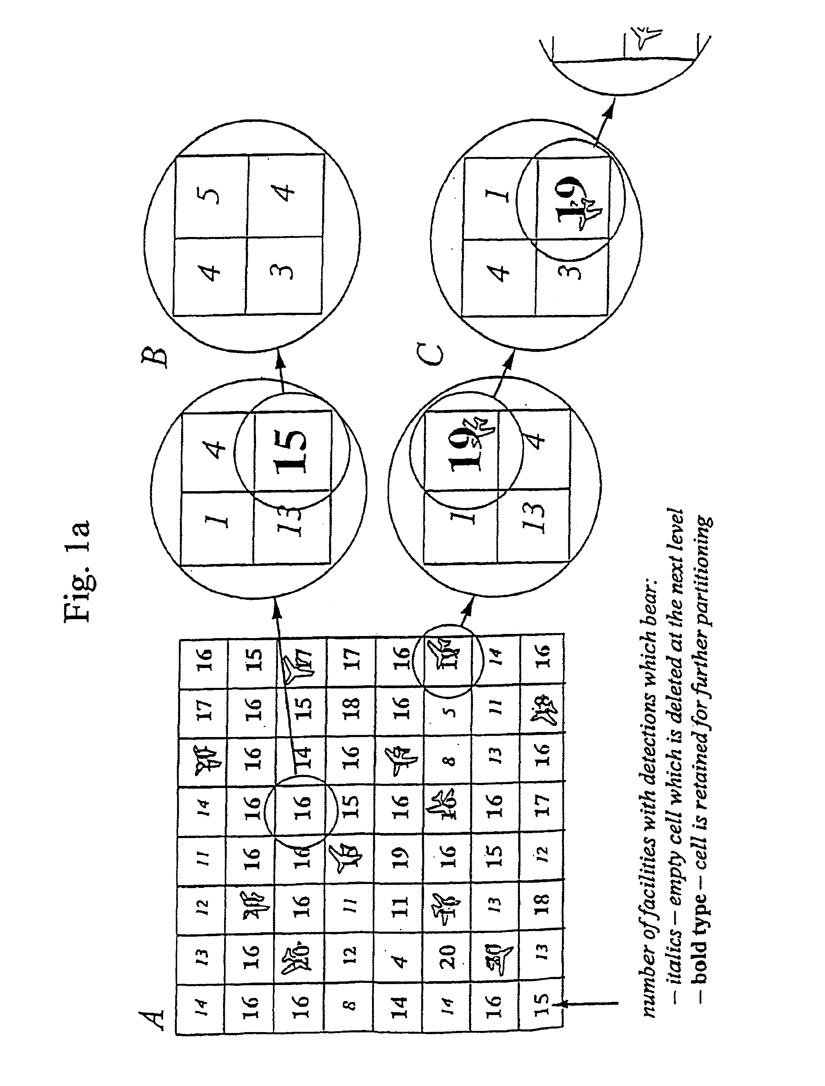
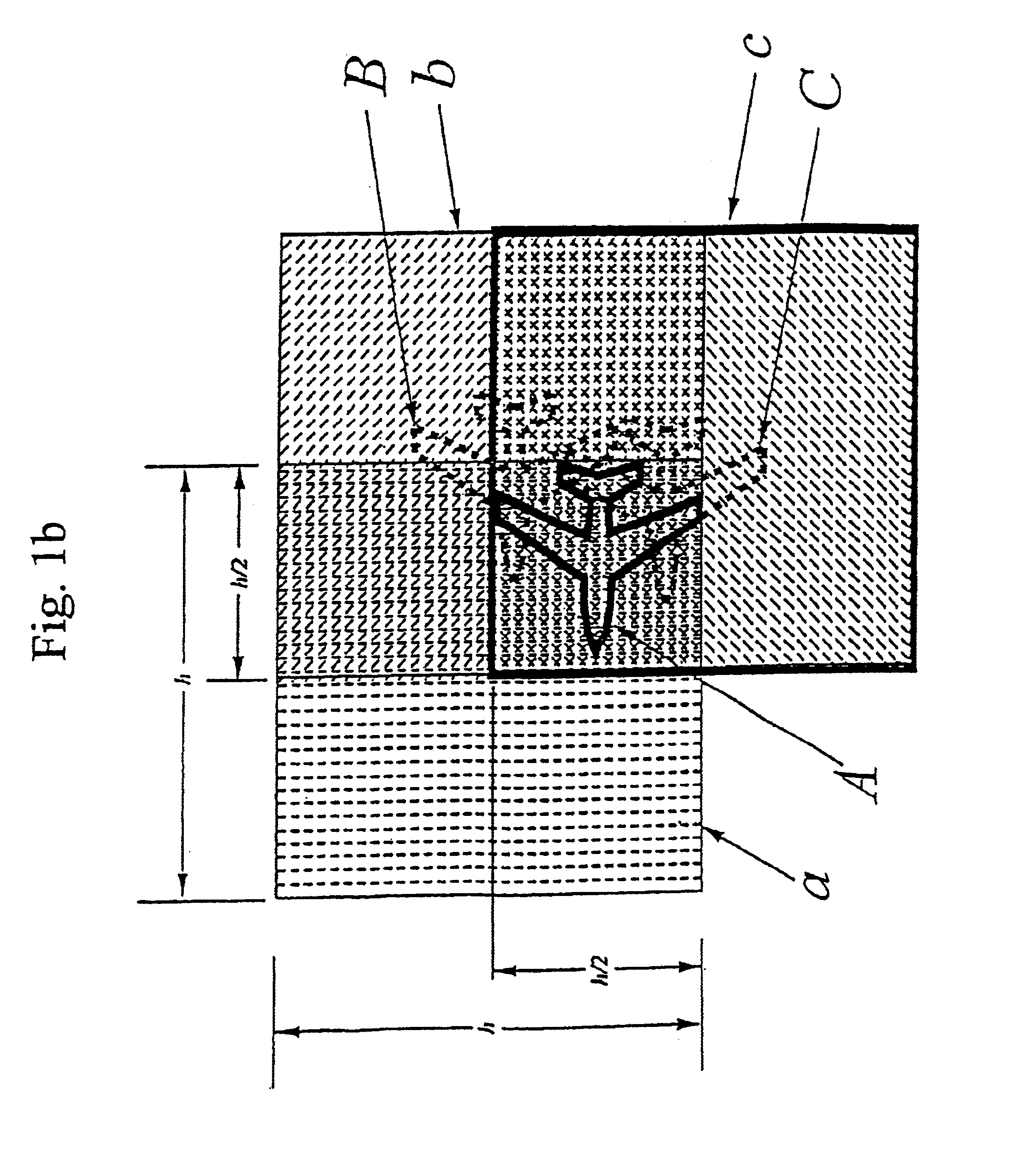
The analysis equipment determines the instant for sending signals, and received signals are parameterised as a function of path of propagation and change in path of propagation between transmission point and reception point according to established principles for radar. Change in path of propagation is approximated thr...


PUM


Abstract

The present invention relates to a system for using signals scattered by targets to determine position and velocity for each of the targets and comprises a set of transmitters and receivers of electromagnetic or acoustic signals, said transmitters and receivers dispersed to known points. Each pair of transmitter and receiver, monostatic or bistatic, is named a measuring facility. The ranges of the transmitters are chosen so that a target at an arbitrary point within the position space can be measured via scattering in the target by at least four measuring facilities. For each measuring facility, target detection occurs with constant false alarm rate in the form of probabilities over resolution cells with regards to range and Doppler velocity and conceivable targets are placed in a 2-dimensional linear space belonging to the measuring facility. The 3-dimensional positions and 3-dimensional Doppler velocities are represented as a 6-dimensional linear position and velocity space subdivided into resolution cells with the same resolution of range and Doppler velocity that is found at the measuring facilities. For each intersection representing detections at at least four measuring facilities the probability is calculated that the intersection is a false alarm emanating intersections between subsets from different targets and when the probability falls below a predefined value, it is given that the intersection contains at least one target. The target positions and target velocities are extracted in this way.”

Description

BACKGROUND OF THE INVENTIONThe present invention relates to a system for using signals scattered by one or more targets to determine position and velocity for each of the targets. The targets are situated in a position space comprising a number of transmitters and receivers of electromagnetic or acoustic signals, these transmitters and receivers being dispersed to a number of known points in the position space. The system will be discussed in the following with respect to a radar application. The invention is however equally suited for use in acoustic systems and it is the stated intention of the applicant that this patent application shall concern such systems as well. The system can in general be used in the case where the positions in space and velocity vectors for a very large number of targets shall be determined.Radar systems of today for surveillance and combat command consist of a small number of long range and capable radar stations. These systems are very vulnerable, partl...

Claims


Application Information

Patent Timeline
Patent Type & Authority Patents(United States)
IPC IPC(8): G01S13/00G01S13/87G01S7/00G01S7/28
CPCG01S13/878G01S13/003G01S7/003G01S7/2813
Inventor HELLSTEN, HANS
Owner TOTALFORSVARETAB FORSKNINGSINSTITUT FOI
Why Eureka
Try Eureka