Integrated inverted F antenna and shield can

a shield can and inverted f technology, applied in the field of radio frequency (rf) devices, can solve the problems of unsatisfactory increase of space requirements for the overall device and package, and achieve the effects of convenient installation, excellent electrical performance and compact siz

Inactive Publication Date: 2005-02-01
VTECH TELECOMM
View PDF8 Cites 40 Cited by
  • Summary
  • Abstract
  • Description
  • Claims
  • Application Information

AI Technical Summary

Benefits of technology

To address the foregoing and other deficiencies in the prior art, the present invention provides an inverted F antenna with an integrated shield can. In a preferred embodiment, the present invention comprises a unitary sheet of electrically conductive material, such as steel, that is cut or stamped into a predetermined shape such that when the cut or stamped sheet is folded, both a shield can (that is pro

Problems solved by technology

Designing devices that incorporate both of these elements (ground plane and shield can)

Method used


Image

  • Integrated inverted F antenna and shield can
  • Integrated inverted F antenna and shield can
  • Integrated inverted F antenna and shield can

Examples


Embodiment Construction

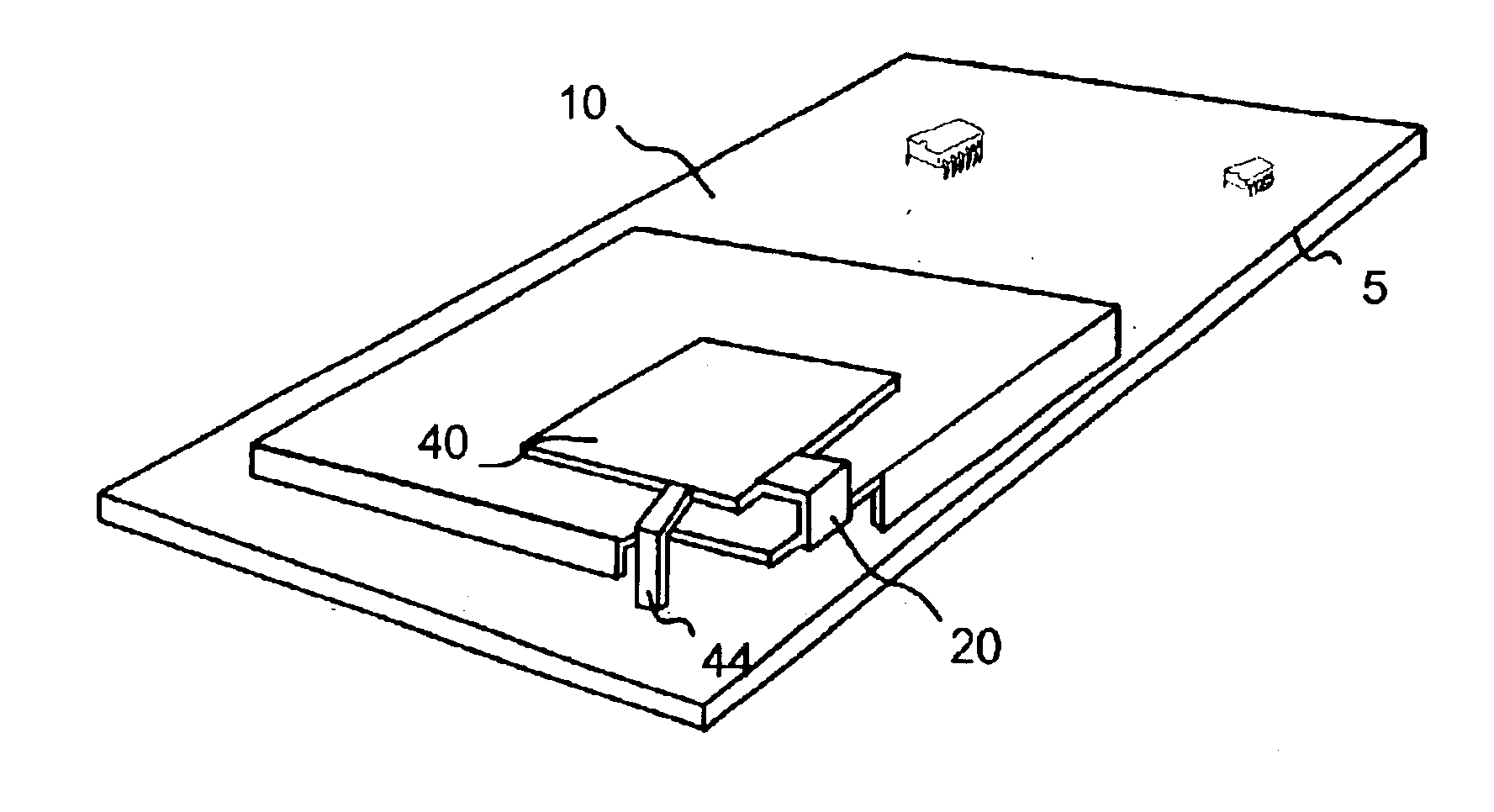
A significant aspect of the present invention is the ability to integrate the functions of both an antenna and shield can. More particularly, the present invention provides a unique configuration by which the functionality of a planar portion of a shield can and an inverted F-antenna ground plane are shared, resulting in a more compact design and excellent electrical performance.

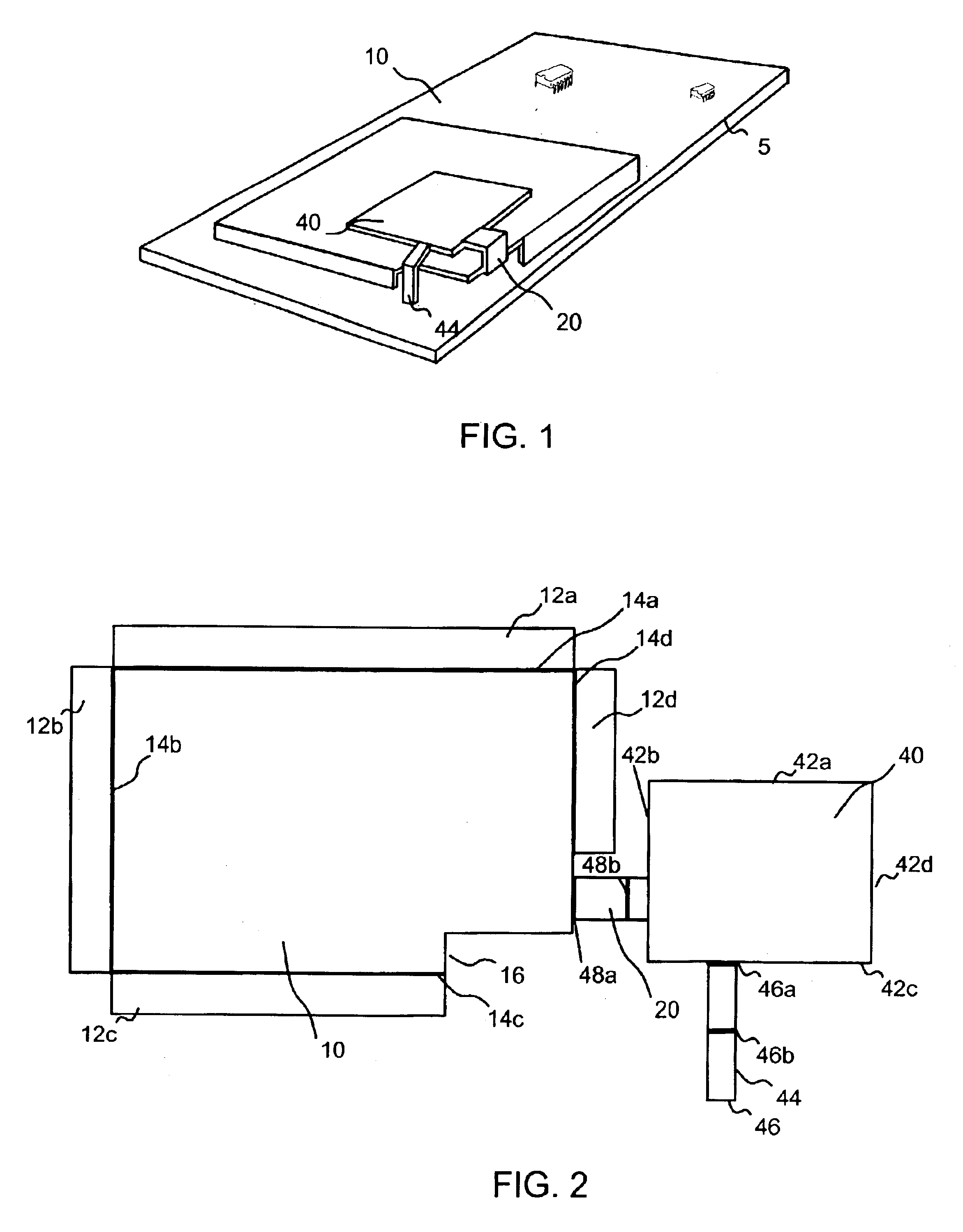
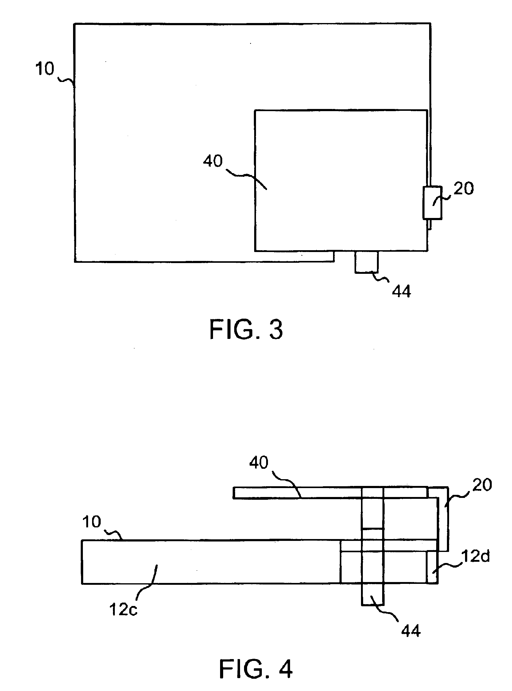
FIG. 1 is a perspective view of the integrated inverted F antenna and shield can mounted to a circuit board 5 according to a preferred embodiment of the present invention. FIG. 2 is a plan view of a single sheet of conductive material 7 prior to folding. FIG. 1 thus depicts sheet 7 of FIG. 2 in a folded configuration whereby both a shield can portion 10 and planar radiating element portion 40 can be easily seen. FIGS. 3-5 show plan, and different side views of the folded device shown in FIG. 1.

Referring again to FIG. 2, sheet 7, which is in a pre-folded state, preferably includes two major portions: a shield...


PUM


Abstract

An inverted F antenna with integrated shield is constructed from an electrically conducting sheet that is folded into a shape that provides both a shield can covers an RF module of circuit and an inverted F antenna such that shield can functions also as a ground plane for the antenna. In a pre-folded state the sheet has a shield can portion and a radiating element portion that are connected to each other by a ground feed line that bridges the shield can portion and radiating element portion. The shield can portion preferably includes a plurality of walls that are foldable along respective folds. The radiating element portion preferably includes a plurality of edges and a signal feed line extending from a first one of the plurality of edges. The ground feed line extends from a second one of said plurality of edges. When the sheet is folded, the radiating element portion is suspended over the shield can portion and is substantially fixed with respect to the shield can portion by the ground feed line and the signal feed line.

Description

BACKGROUND1. Field of the InventionThe present invention relates generally to radio frequency (RF) devices, and more particularly to inverted F antennas, shield cans and related circuitry and devices.2. Background of the InventionPlanar inverted F antennas generally include at least one planar radiating element and a ground plane in a plane parallel to the radiating element. A short ground tab typically joins the radiating element to the ground plane. In one known configuration, as exemplified by the structure shown in U.S. Pat. No. 6,218,991 to Sanad, the radiating element is fed via a separate center pin that is located within a periphery of the ground plane. In this design, the short ground tab is also located within the periphery of the ground plane. Also, in Sanad's device, the radiating element, ground plane, center pin and short ground tab are all separate components that must be assembled together.In another known configuration, like that shown in FIG. 1 of U.S. Pat. No. 6,2...

Claims


Application Information

Patent Timeline
IPC IPC(8): H01Q9/04H01Q1/24H01Q1/52H01Q23/00H01Q1/00H05K9/00
CPCH01Q1/243H01Q1/526H05K9/002H01Q23/00H01Q9/0421
Inventor WONG, ARGUS C. W.LEUNG, WAI HUNG
Owner VTECH TELECOMM
Why Eureka
Try Eureka