System for dissipating electrical charge from a cabinet of an electronic apparatus

a technology for electronic devices and cabinets, applied in the direction of electrical apparatus casings/cabinets/drawers, identification means, instruments, etc., can solve the problems of static electricity causing a sudden current flow, user discomfort, user discomfort, etc., to reduce the impact of static electricity, prevent the generation of high voltage, and effectively ground the metal portion of the cabin

Inactive Publication Date: 2005-02-01
SONY CORP
View PDF12 Cites 4 Cited by
  • Summary
  • Abstract
  • Description
  • Claims
  • Application Information

AI Technical Summary

Benefits of technology

An object of the present invention is therefore to provide an electronic apparatus having a cabinet that is made of metal partially or entirely which can effectively ground the metal portion of the cabinet and cope with an indirect lightning stroke or the like while reducing impact of static electricity and preventing generation of a high voltage.
Therefore, by providing the above parallel circuit in the discharge path of the cabinet, in the electronic apparatus having the metal cabinet, it becomes possible to effectively ground the metal portion of the cabinet while reducing impact of static electricity and preventing generation of a high voltage.

Problems solved by technology

However, where the metal member and the ground portion are directly connected to each other as mentioned above, static electricity causes a sudden flow of current when a user touches the electronic apparatus.
This causes a problem that the user feels unpleasant.
This also results in a problem that discharge or the like causes a user to feel unpleasant.

Method used


Image

  • System for dissipating electrical charge from a cabinet of an electronic apparatus
  • System for dissipating electrical charge from a cabinet of an electronic apparatus
  • System for dissipating electrical charge from a cabinet of an electronic apparatus

Examples


first embodiment

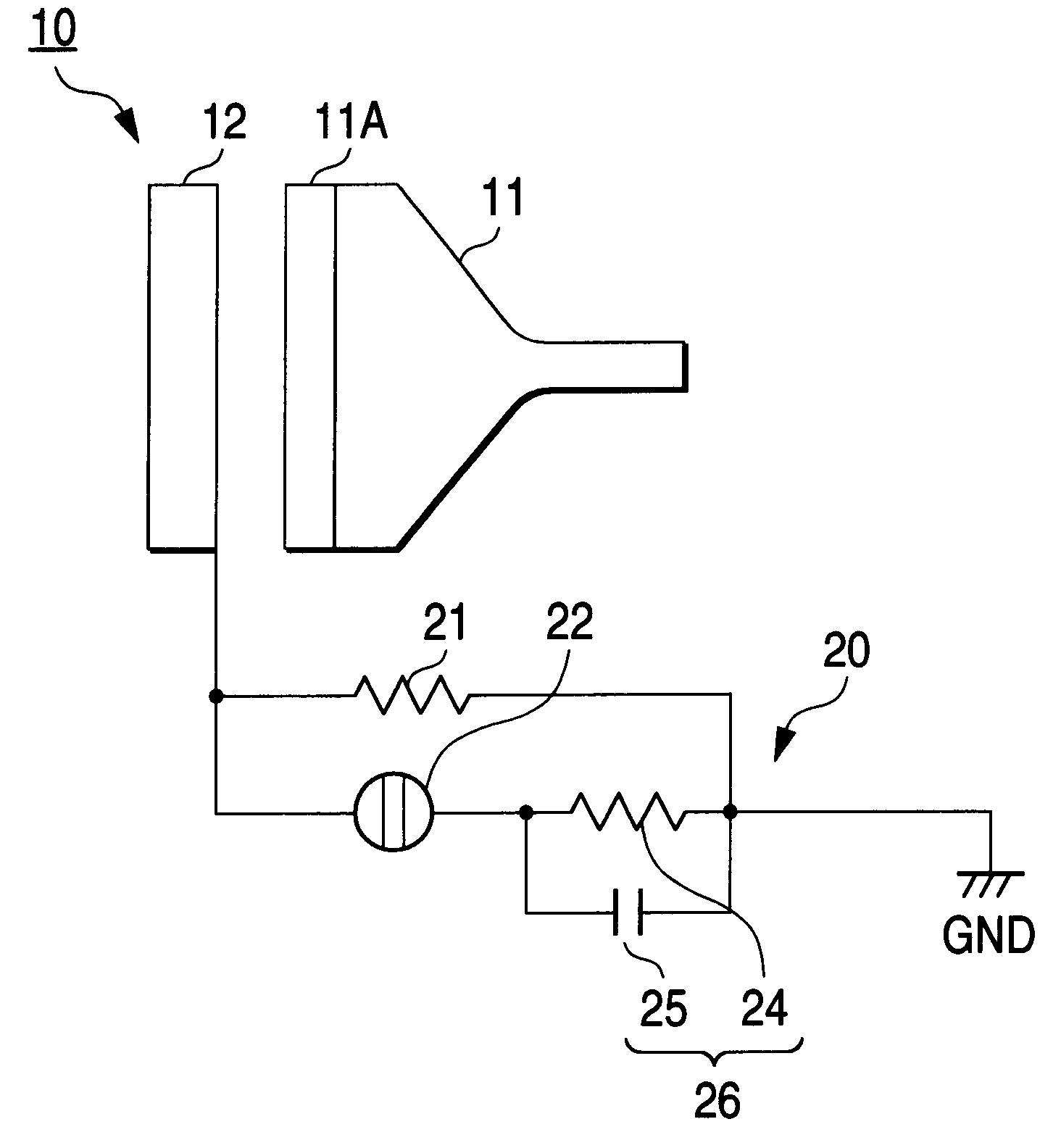
FIG. 1 is a schematic diagram showing the configuration of an electronic apparatus according to the invention.

The electronic apparatus according to this embodiment is a TV receiver 10 using a CRT 11. The TV receiver 10 has a front cabinet 12 that surrounds the outer circumferential portion of a face panel 11A of the CRT 11. The front cabinet 12 is made of metal.

That is, by using the metal front cabinet 12, the TV receiver 10 of this embodiment is advantageous in design over TV receivers using a front cabinet made of a synthetic resin and realizes a product specification with an image of a higher grade than in the case of using a synthetic resin.

The TV receiver 10 is provided with a chassis board (not shown) that is mounted with various circuit parts, a back cabinet (not shown), etc. The chassis board is provided with a ground portion GND, which serves to ground the entire TV receiver 10 by using a power line.

A discharge path 20 is provided between the front cabinet 12 and the ground...

second embodiment

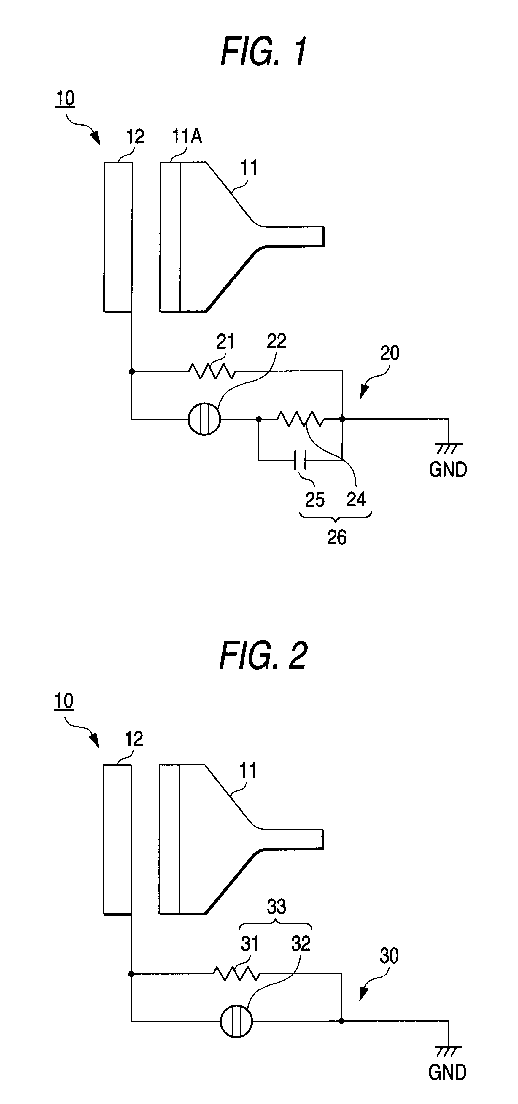
FIG. 2 is a schematic diagram showing the configuration of an electronic apparatus according to the invention. The components in FIG. 2 having the same components in FIG. 1 are given the same reference numerals as the latter and will not be described.

As in the case of the first embodiment, this embodiment is directed to a TV receiver 10 using a CRT 11 that has a metal front cabinet 12.

In this TV receiver 10, a discharge path 30 between the front cabinet 12 and the ground portion GND has a parallel circuit 33 consisting of a resistor 31 and a discharge tube 32.

Inserted between the front cabinet 12 and the ground portion GND, the resistor 31 serves to absorb a current of CRT discharge that occurs constantly.

Connected in parallel to the resistor 31, the discharge tube 32 discharges at a voltage of 7 kV, for example.

The parallel circuit 33 having the above structure effectively discharges a voltage that occurs at the front cabinet 12 side and thereby keeps the front cabinet 12 side at a...

third embodiment

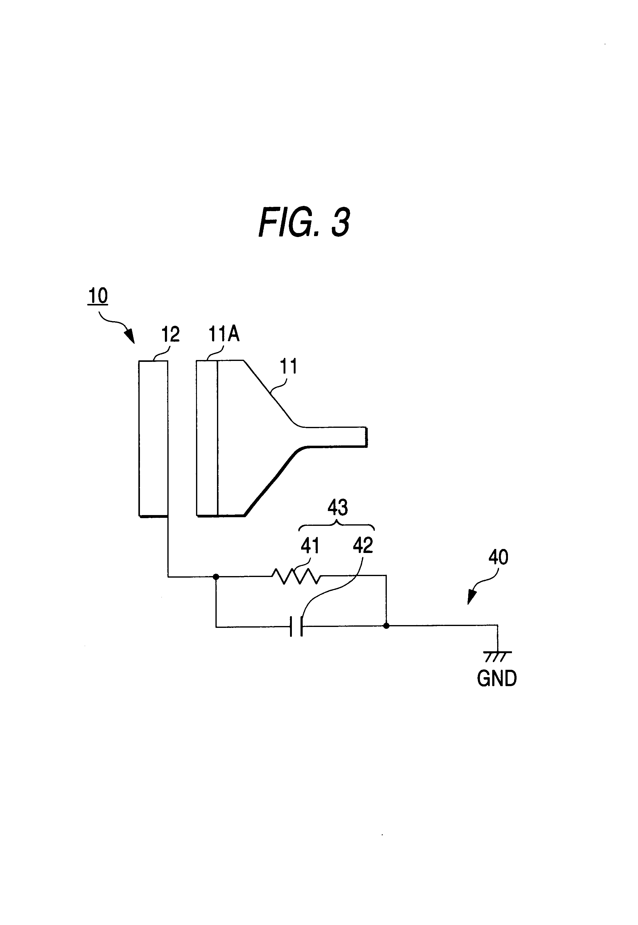
FIG. 3 is a schematic diagram showing the configuration of an electronic apparatus according to the invention. The components in FIG. 3 having the same components in FIG. 1 are given the same reference numerals as the latter and will not be described.

As in the case of the first embodiment, this embodiment is directed to a TV receiver 10 using a CRT 11 that has a metal front cabinet 12.

In this TV receiver 10, a discharge path 40 between the front cabinet 12 and the ground portion GND has a parallel circuit 43 consisting of a resistor 41 and a capacitor 42.

Inserted between the front cabinet 12 and the ground portion GND, the resistor 41 absorbs a current of CRT discharge that occurs constantly. The capacitor 42 is connected in parallel to the resistor 41.

The parallel circuit 43 having the above structure effectively discharge a voltage occurring at the front cabinet 12 side and thereby keeps the front cabinet 12 side at a low potential. Further, the parallel circuit 43 prevents a sudd...


PUM


Abstract

A TV receiver having a metal front cabinet is provided with a discharge path between the front cabinet and a ground portion of the TV receiver. The discharge path includes a series circuit in which a discharge tube is connected in series to a parallel circuit of a first resistor and a high-voltage capacitor and a second resistor that is connected in parallel to the series circuit. The discharge path effectively discharges a voltage occurring at the front cabinet via the second resistor while preventing a sudden flow of current and reducing the influence of static electricity. The series circuit in which the discharge tube is connected in series to the parallel circuit of the first resistor and the high-voltage capacitor has a function of causing high-voltage pulses occurring at the ground portion GND to escape to the front cabinet while converting those into pulses having a low voltage level.

Description

BACKGROUND OF THE INVENTION1. Field of the InventionThe present invention relates to an electronic apparatus having a cabinet that includes a metal portion.2. Description of the Related ArtConventionally, for example, in many of TV receivers using a CRT, a cabinet that surrounds the outer circumferential portion of the face panel of the CRT is made of a synthetic resin.However, there occurs a case that to provide a product with a high-grade image or improve design performance it is desired to use a metal cabinet. In this case, it is necessary to ground the metal cabinet.To this end, methods are employed in which a metal member such as a cabinet as mentioned above and a ground portion that is provided on a chassis board of an electronic apparatus are directly connected to each other or connected to each other via a resistor.However, where the metal member and the ground portion are directly connected to each other as mentioned above, static electricity causes a sudden flow of current...

Claims


Application Information

Patent Timeline
Patent Type & Authority Patents(United States)
IPC IPC(8): H01J29/86H05F3/02H04N5/64G09F9/00H02H9/06H04N5/65H05F3/04
CPCH05F3/02H01J29/868H04N5/65
Inventor SUGIURA, YUTAKAKANEKO, TADASHI
Owner SONY CORP
Why Eureka
Try Eureka