
Data slicer for combined trellis decoding and equalization

a data slicer and data equalization technology, applied in the field of data slicers or quantizers, can solve the problems of prohibitive delays for dfe, signal distortion that may occur in the transmitter, and delay the decision on what symbol was transmitted by several symbol periods

Inactive Publication Date: 2005-02-01
AVAGO TECH WIRELESS IP SINGAPORE PTE
View PDF8 Cites 35 Cited by
  • Summary
  • Abstract
  • Description
  • Claims
  • Application Information

AI Technical Summary

Problems solved by technology

These effects are commonly referred to as channel impairments and include signal distortion that may occur in the transmitter, in the receiver or in the channel through which the signal is transmitted.
The use of such a decoder, however, delays the decision on what symbol was transmitted by several symbol periods.
These delays can be prohibitive for the DFE, since it relies on canceling the inter-symbol-interference of the previous symbols on the current symbol by using previously available decisions.
A typical problem with using only a slicer in a DFE is a loss in performance due to incorrect decisions.
Because an incorrect decision used in the DFE to remove inter-symbol interference (ISI) can cause further errors, this performance loss is known as “error propagation.”
The implementation complexity of these approaches, however, is significant and may undesirably add to the cost of the decoder.
The pilot signal of a VSB signal, is not a good reference, however, as it may be corrupted both in frequency and phase by multipath distortion.
In addition, the system disclosed by Willming may not operate properly when used with VSB signals that do not have pilot signals.

Method used


Image

  • Data slicer for combined trellis decoding and equalization
  • Data slicer for combined trellis decoding and equalization
  • Data slicer for combined trellis decoding and equalization

Examples


case 1

emory=2

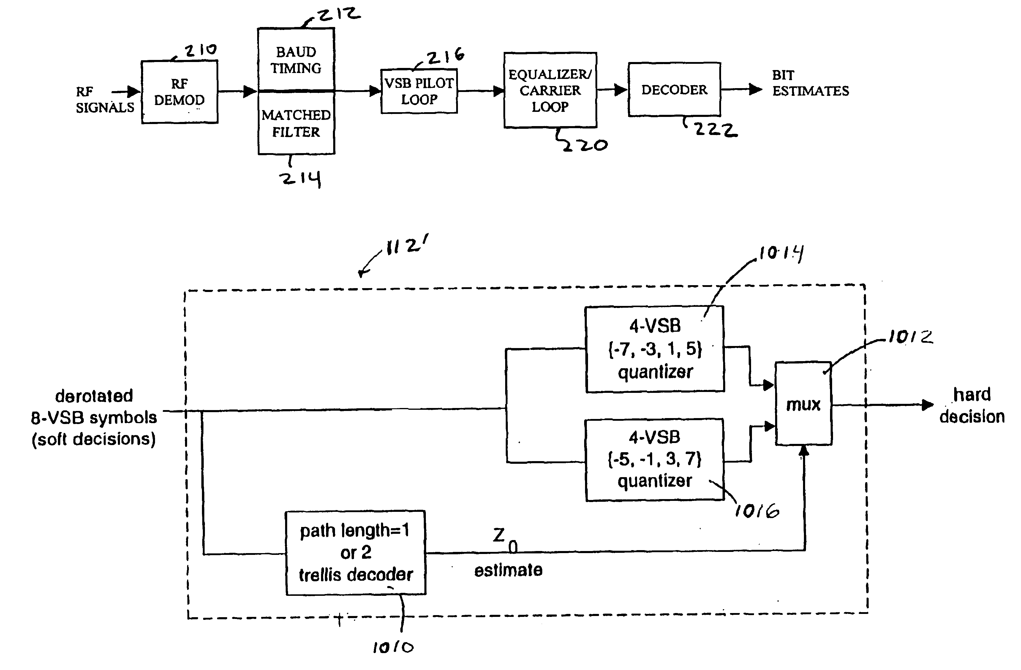
In this case, the Z0(n) estimate is based on path metrics p0(n), p1(n), P2(n), p3(n). If the minimum path metric, p, among {p0(n), p1(n), P2(n), p3(n)} corresponds to either states 0 or 1 (i.e. p0(n) or p1(n)) then the estimate for Z0(n) equals 0, otherwise the estimate equals 1. The rationale for this selection is based on equation (2) above. This case may be described by equation (12).

Z0(n)=0 if minimum {p0(n), p1(n)}<minimum {p2(n), p3(n)} (12) =1 otherwise

Case 2: Path Memory 1

In this case, the Z0(n) estimate is based on path metrics p0(n-1), p 1(n−1), p2(n-1), p3(n-1). If the minimum path metric among {p0(n-1), p1(n-1), p2(n-1), p3(n−1)} corresponds to either states 0 or 2, then the estimate for Z0(n) equals 0, otherwise the estimate equals 1. The rationale for this selection is based on equation (1) above. This case may be described by equation (13)

Z0(n)=0 if minimum {p0(n−1), p2(n−1)}<minimum {p1(n−1), p3(n−1)}  (13) =1 otherwise.

Clearly the advantage of this ...

case 3

emory=2, (low complexity)

In this case, the estimate of Z0(n) is based on path metrics {p0(n−1), p1(n−1), p2(n−1), p3(n−1)}, and on ‘extending’ the two best states corresponding to the minimum two path metrics from among {p0(n−1), p1(n−1), p2(n−1), p3(n−1)}. In this case, the possible results are given by the conditional statements shown in Tables 1 and 2.

TABLE 1If p0(n − 1) and p2(n − 1) are the best states then Z0(n) = 0If p1(n − 1) and p3(n − 1) are the best states then Z0(n) = 1

TABLE 2If p0(n − 1) and p1(n − 1) are the best states thenif minimum {p0(n − 1) + bm(‘a’), p0(n − 1) + bm(‘b’)}<minimum {p1(n − 1) + bm(‘c’), p1(n − 1) + bm(‘d’)} thenZ0(n) = 0else Z0(n) = 1

It is possible to simplify the final computation in Table 2 to:if p0(n−1)+bm(‘ab’)<p1(n−1)+bm(‘cd’) then Z0(n)=0else Z0(n)=1

Where bm(‘ab’) is given by equation (14) and bm (‘cd’) is given by equation (15).

bm(‘ab’)=Euclidean distance (current sample, Z0=0 slicer)=Euclidean distance(current sample, {−7,−3,1,5}) ...


PUM


Abstract

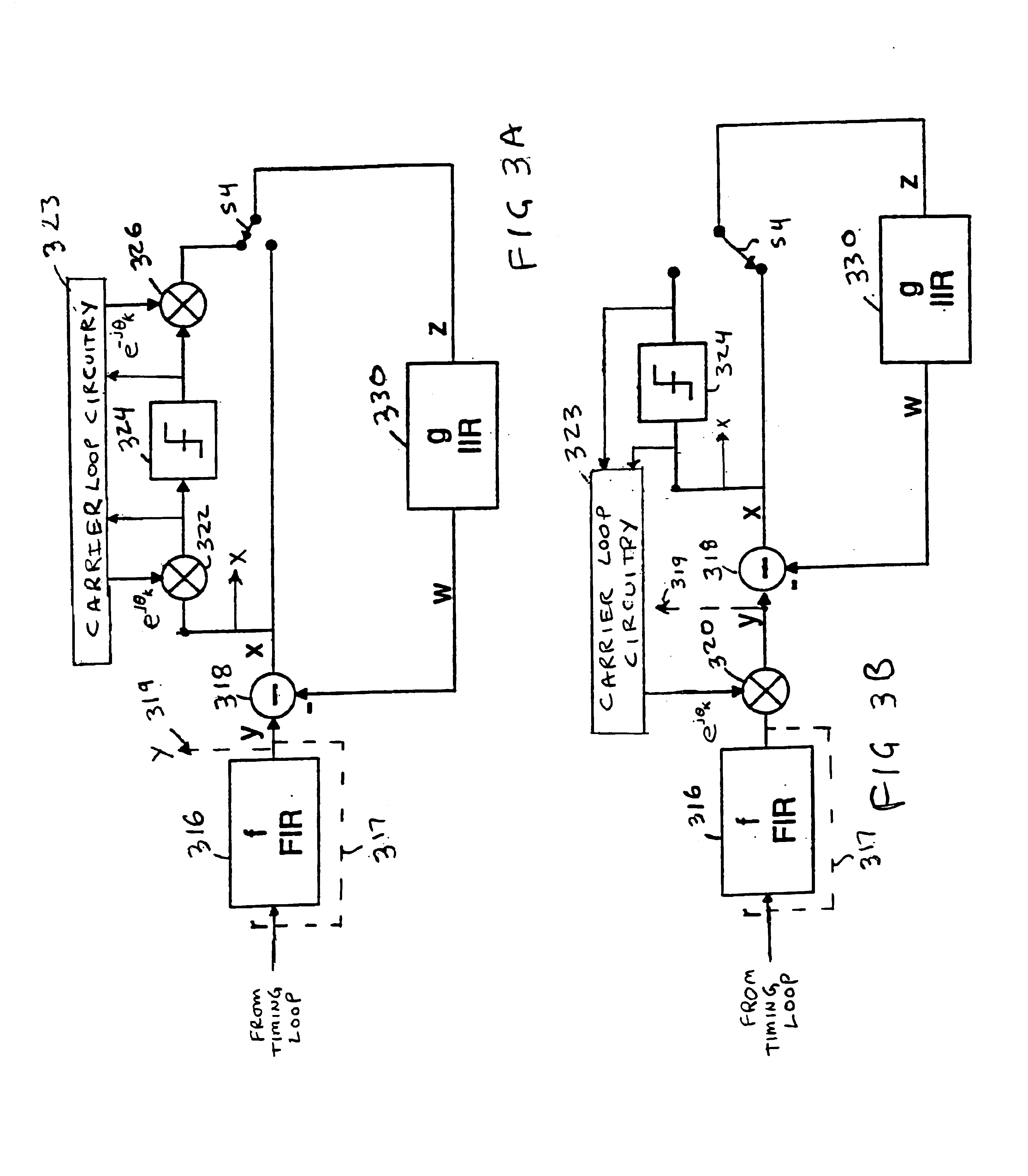
A slicer for a decision feedback error equalizer system that processes trellis encoded data using the ATSC trellis code is implemented in two parts. A first part includes a trellis decoder that estimates a single bit of the symbol. The second part includes two partial trellis decoders. A multiplexer directs the received digital samples to one of the two trellis decoders responsive to the estimated symbol. An alternative slicer estimates two bits of the output symbols and selects from among four decoders to fully decode the symbols. The slicer is used in an equalizer having adaptive filters that may operate either on passband or baseband signals. The slicer is used both to recover the carrier signal on which the symbols are modulated and to provide symbols to the second filter that are used to determine filter coefficients for the second filter.

Description

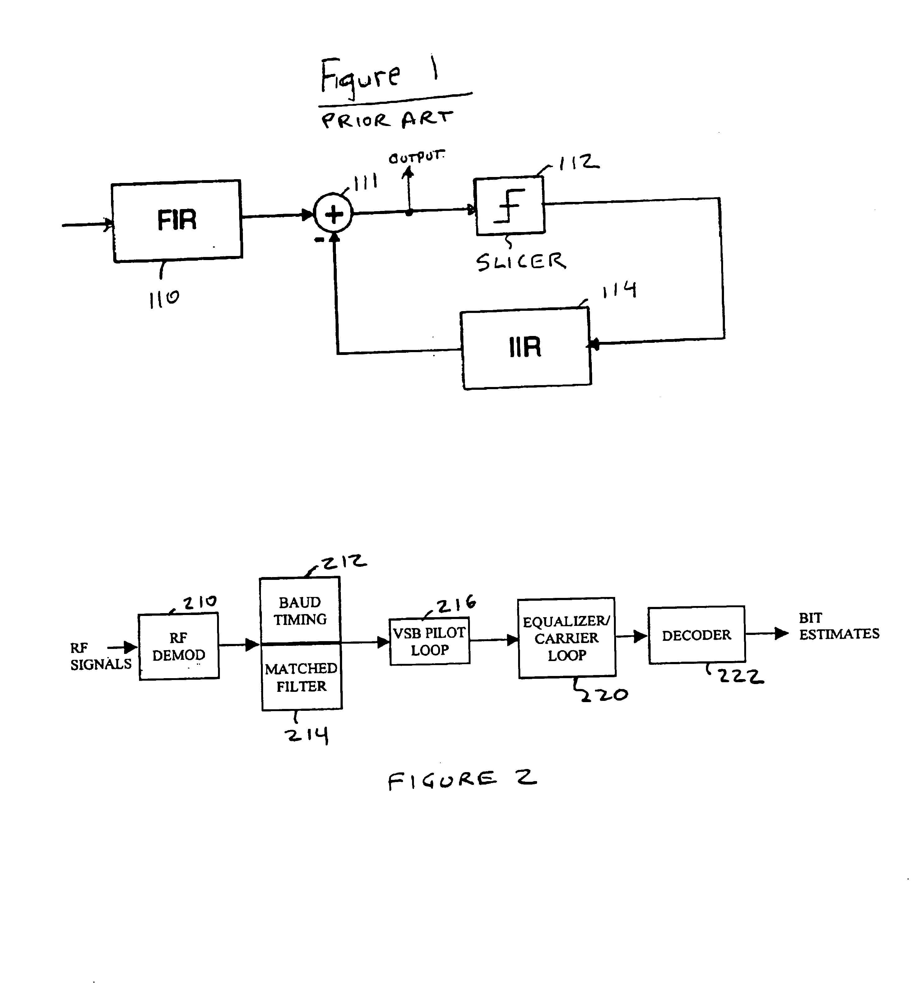
BACKGROUND OF THE INVENTIONThe present invention concerns data slicers or quantizers and in particular, a data slicer suitable for use in a baseband or passband decision-feedback equalizer.Equalizers are typically used in coded digital communications systems to compensate for multipath / linear filtering effects caused by the transmission channel. These effects are commonly referred to as channel impairments and include signal distortion that may occur in the transmitter, in the receiver or in the channel through which the signal is transmitted. The equalizer is an adaptive filter, often implemented as a finite impulse response (FIR) filter, an infinite impulse response (IIR) filter or a combination of FIR and IIR filters. Each filter has a plurality of coefficients that are adapted to minimize an error criterion. This error criterion may be, for example, the mean-square error between a transmitted training signal and the received training signal. A typical equalizer maintains a copy ...

Claims


Application Information

Patent Timeline
IPC IPC(8): H04L25/03H04L27/38H04L27/00H04L1/00
CPCH04L1/0054H04L1/006H04L25/03057H04L27/0008H04L27/38H04L2025/03732H04L2025/0342H04L2025/03566H04L2025/03617H04L2025/0363H04L2025/03382
Inventor HULYALKAR, SAMIR N.ENDRES, THOMAS J.SCHAFFER, TROY A.STROLLE, CHRISTOPHER H.
Owner AVAGO TECH WIRELESS IP SINGAPORE PTE
Learn More