Microstructured optical fiber and method of making

a microstructured optical fiber and fiber technology, applied in the field of fiber optic waveguides, can solve the problem that the sub medium is not necessarily able to constitute an optical fiber by itself, and achieve the effects of reducing the influence of surface tension, small effective core area, and increasing curvature radii

Inactive Publication Date: 2005-02-01
SUMITOMO ELECTRIC IND LTD
View PDF5 Cites 10 Cited by
  • Summary
  • Abstract
  • Description
  • Claims
  • Application Information

AI Technical Summary

Benefits of technology

The present invention fulfills the above described fiber characteristic needs, while overcoming the drawbacks of the prior art, at least in part, by offsetting sub medium regions from the lattice points of periodical lattice in the innermost region of the fiber to form the core region. As a result, it becomes possible to realize valuable characteristics such as zero or negative chromatic dispersion, zero or negative chromatic dispersion slope, and small effective core area with a structure in which the curvature radii of sub medium regions are larger than those of the prior art. Increase in curvature radii of sub medium regions reduces the influence of surface tension during fiber drawing, resulting in a high controllability of the fiber structure and optical characteristics, a high yield of production, a low transmission loss, and a high durability against UV radiation.

Problems solved by technology

On the other hand, a sub medium is not necessarily able to constitute an optical fiber by itself.

Method used


Image

  • Microstructured optical fiber and method of making
  • Microstructured optical fiber and method of making
  • Microstructured optical fiber and method of making

Examples


first embodiment

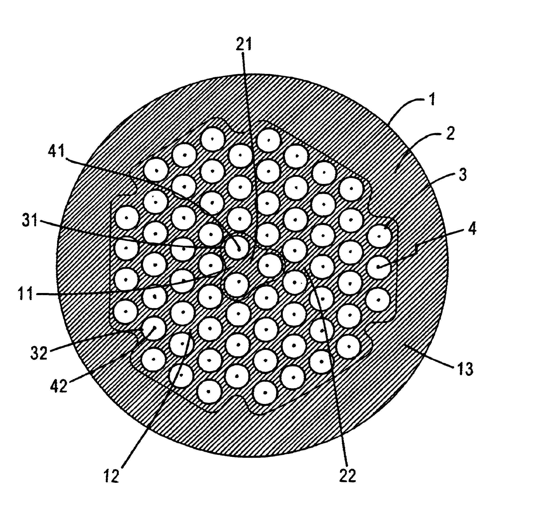
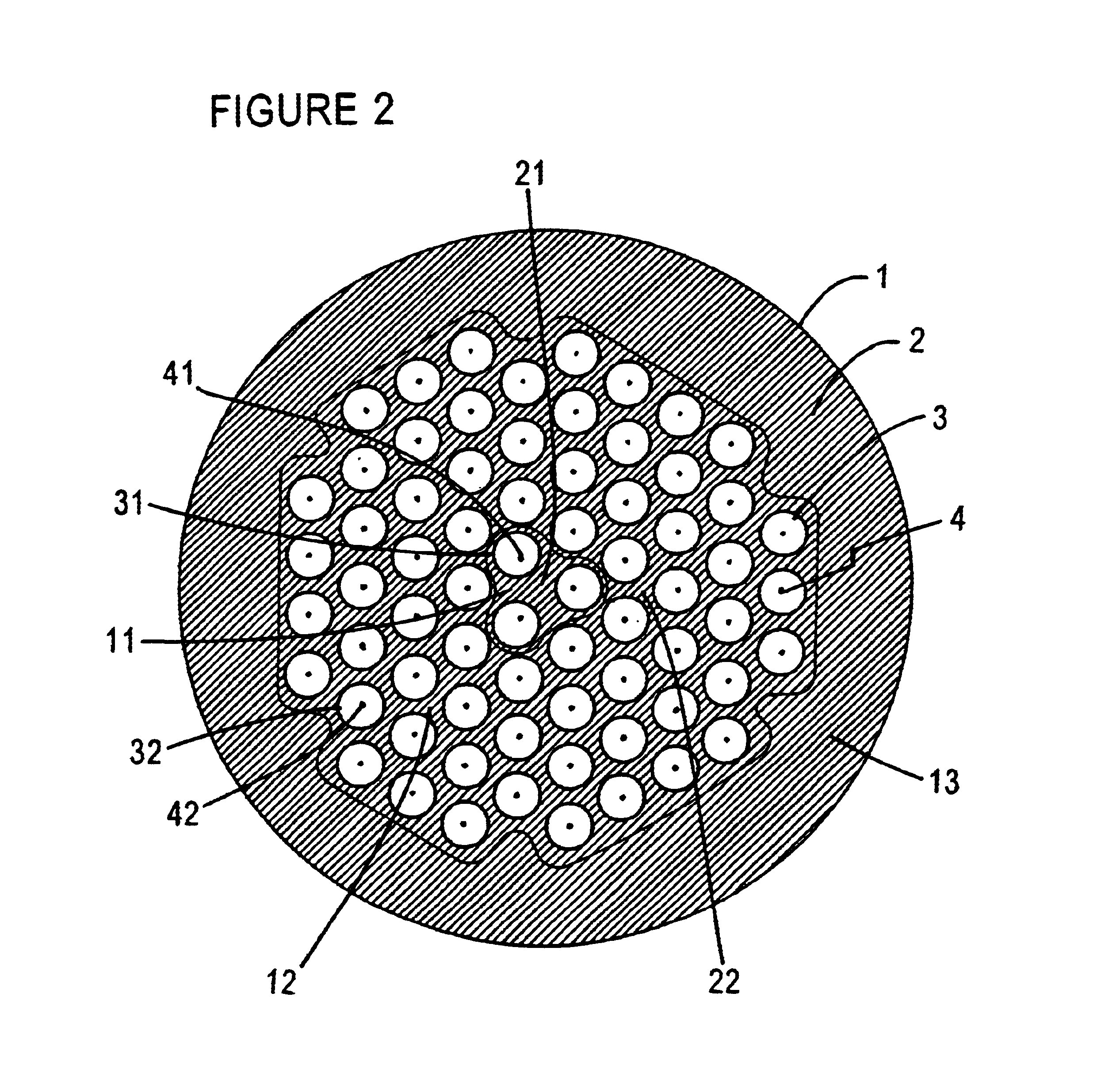
FIG. 2 shows the cross section of an optical fiber 1 of the present invention, in which a plurality of holes 3, which are sub medium regions, are arranged in silica glass 2, which is a main medium. The cross section has an inner region 11 and an outer region 12 surrounding the inner region. The arrangement of the holes is substantially a hexagonal lattice. In the outer region, the centers of the holes 32 substantially coincide with the outer lattice points 42, which are a part of the lattice points 4 of a hexagonal lattice and are located in the outer region. On the other hand, in the inner region, the centers of the holes 31 are apart from the inner lattice points 41 by approximately 0.1 lattice period outward. The inner lattice points are a part of the lattice points 4 of the hexagonal lattice and are located in the inner region. The diameters of the holes 31 and 32 are substantially uniform in the cross section. For each lattice cell of the lattice point 41 or 42, a single hole 3...

second embodiment

FIG. 6 shows the cross section of an optical fiber 1a of the present invention. In this structure, a plurality of holes 3a are arranged in silica glass 2a, and the holes 32a in the outer region 12a are arranged so that there centers coincide with respective lattice points 42a, which are a part of the lattice points 4a of a hexagonal lattice and located in the outer region, and consequently the arrangement possesses a two-dimensional translational symmetry. Other media having appropriate refractive indices may be used in lieu of holes. Because of the two-dimensional translational symmetry, it is possible to localize a lightwave in the inner region 11a by Bragg reflection and guide it over the fiber. Since the arrangement of the holes 32a is periodical in the outer region 12a, the outer region 12a can reflect a lightwave belonging to a certain range of frequencies and propagation constant by Bragg reflection. Although such a lightwave cannot propagate in the outer region 12a, since th...

third embodiment

FIG. 8 shows the cross section of an optical fiber 1c of the invention. In the optical fiber 1c, a plurality of holes 3c are arranged in silica glass 2c. The cross section has an inner region 11c and an outer region 12c surrounding the inner region. In this embodiment, the arrangement of the holes is substantially a square lattice. In the outer region 12c, the centers of holes 32c are located at the outer lattice points 42c, which are a part of lattice points 4c of the square lattice and are located in the outer region 12c. On the other hand, in the inner region 11c, the centers of holes 31c are located apart from the inner lattice points 41c by approximately 0.1 lattice period outward. The inner lattice points 41c are a part of lattice points 4c of square lattice and are located in the inner region 11c. For each lattice cell of the lattice point 41c or 42c, a single hole 31c or 32c has its center in the cell. The outer region 12c is further surrounded by a jacket region 13c. Althou...


PUM

PropertyMeasurementUnit
radiiaaaaaaaaaa
curvature radiiaaaaaaaaaa

Abstract

A microstructured optical fiber is structured with a core region and a cladding region surrounding the core region. A cross section of the fiber portion conforms to a translationally symmetric lattice, a center of each sub medium region in the outer region coinciding with respective lattice points, and a plurality of sub medium regions in the inner region having centers that are offset from respective lattice points.

Description

FIELD OF THE INVENTIONThe present invention relates to fiber optic waveguides, more particularly to arrangements of sub medium regions in microstructured optical fibers.BACKGROUNDThe recent development of the microstructured optical fiber, in which a high index core region is surrounded by cladding having a mix of silica and air, offers new fiber properties by virtue of the large refractive-index contrast that exists between glass and air. A cladding structure may have a spatially uniform average refractive index that can be adjusted to meet a desired relationship with the core index. FIG. 1 illustrates a prior art microstructured optical fiber in cross section. In the optical fiber 1b, a plurality of holes 3b are arranged in silica glass 2b. The diameters of the holes 3b are substantially uniform in the cross section and the centers of the holes 3b substantially coincide with the lattice points 4b of a hexagonal lattice. With substantially periodically arranged sub medium regions i...

Claims


Application Information

Patent Timeline
Patent Type & Authority Patents(United States)
IPC IPC(8): C03B37/012C03C13/04G02B6/00G02B6/02
CPCC03B37/0122C03B37/01231G02B6/02357C03C13/04G02B6/02028G02B6/02238C03B2201/31C03B2203/14C03B2203/16G02B6/02247C03B2203/42Y02P40/57G02B6/00
Inventor HASEGAWA, TAKEMI
Owner SUMITOMO ELECTRIC IND LTD
Why Eureka
Try Eureka