Variable-wavelength light source unit

a light source unit and variable wavelength technology, applied in the direction of optical radiation measurement, instruments, spectrometry/spectrophotometry/monochromators, etc., can solve the problem of affecting the stability of output light wavelengths, and achieve the effect of shortened measuring tim

Inactive Publication Date: 2005-02-01
YOKOGAWA ELECTRIC CORP
View PDF3 Cites 1 Cited by
  • Summary
  • Abstract
  • Description
  • Claims
  • Application Information

AI Technical Summary

Benefits of technology

It is an object of the invention to provide stable light output wavelength accuracy over a wide range of wavelengths while the light output level of a variable-wavelength light source unit is kept constant.
A semiconductor laser diode of the variable-wavelength light source section is driven by a constant current, whereby the drive current value of the semiconductor laser diode is constant, so that providing a wide range of wavelengths is not inhibited.
A characteristic for canceling out the wavelength dependency of the photocoupler and an optical power monitor photodiode forming the feedback system by the compensator is previously stored in a table. Thus, the wavelength dependency of the photocoupler 3, the optical power monitor PD 7, etc., can be easily canceled out.
Thus, if the wavelength sweeping of the variable-wavelength light source is speeded up, it is made possible to correct the wavelength dependency following the speed, and the measuring time can be shortened.

Problems solved by technology

However, in the technique in FIG. 2, to correct the wavelength and output level, the drive current of the laser diode is controlled, resulting in a factor impairing the stability of the output light wavelength.

Method used


Image

  • Variable-wavelength light source unit
  • Variable-wavelength light source unit
  • Variable-wavelength light source unit

Examples


Embodiment Construction

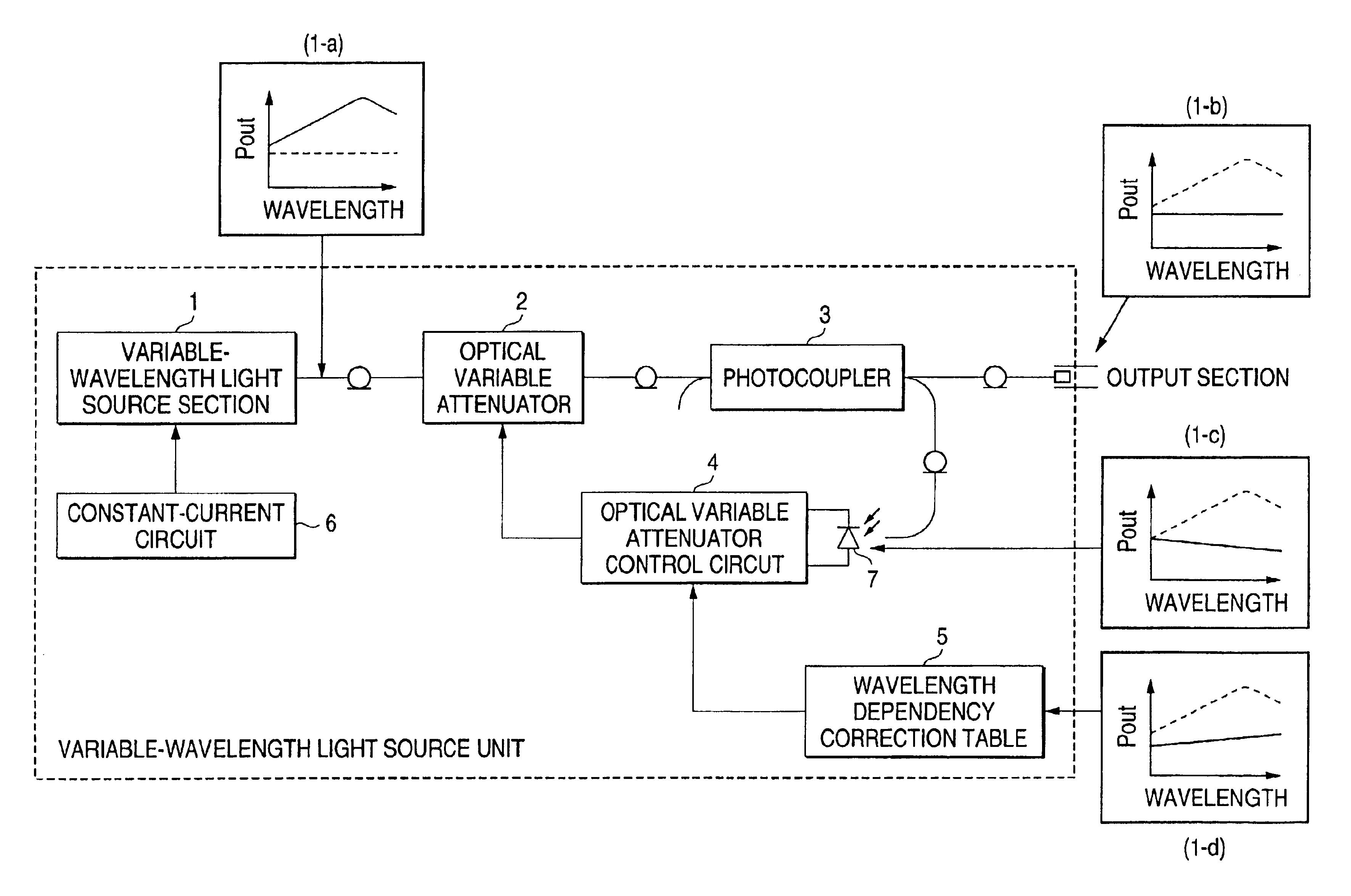
The present invention will be described with reference to the accompanying drawings. A variable-wavelength light source unit of the invention will be discussed with reference to FIG. 1.

In FIG. 1, the variable-wavelength light source unit of the invention is surrounded by the dotted line.

The variable-wavelength light source unit includes a variable-wavelength light source section 1, a constant-current circuit 6, an optical variable attenuator 2, a photocoupler 3, an optical power monitor PD (photodiode) 7, a wavelength dependency correction table 5, and an optical variable attenuator control circuit 4.

In the configuration in FIG. 1, the variable-wavelength light source section 1 is driven by the constant-current circuit 6. Output of the variable-wavelength light source section 1 is emitted through the optical variable attenuator 2 and the photocoupler 3 to the outside.

The optical variable attenuator 2 attenuates (controls) the light output from the variable-wavelength light source se...


PUM

PropertyMeasurementUnit
variable-wavelengthaaaaaaaaaa
wavelengthaaaaaaaaaa
wavelength dependencyaaaaaaaaaa

Abstract

A variable-wavelength light source unit for sending output light of an arbitrary wavelength selected in a variable-wavelength light source section 1 has an optical variable attenuator 2 placed on the output side of the variable-wavelength light source section and a control circuit 4 for controlling the attenuation amount of the optical variable attenuator in response to light output provided by splitting a part of the output light.

Description

BACKGROUND OF THE INVENTION1. Field of the InventionThis invention relates to a variable-wavelength light source unit used for evaluating and manufacturing an optical communication system and an optical device.2. Description of the Related ArtA variable-wavelength light source unit in the related art will be discussed with reference to FIG. 2.In FIG. 2, the variable-wavelength light source unit in the related art is surrounded by the dotted line.The variable-wavelength light source unit includes a variable-wavelength light source section 11, a photocoupler 13, an optical power monitor PD (photodiode) 17, and a drive current control circuit 14.In the configuration in FIG. 2, output of the variable-wavelength light source section 11 is emitted through the photocoupler 13 from an output section of the light source unit.A part of output light split by the photocoupler 13 is fed into the optical power monitor PD (photodiode) 17.Output of the power monitor PD 17 is fed into the drive curr...

Claims


Application Information

Patent Timeline
Patent Type & Authority Patents(United States)
IPC IPC(8): H01S5/0683H01S5/00H01S5/14G02F1/03
CPCH01S5/0683H01S5/146H01S5/143
Inventor EMA, NOBUAKISAITO, HIROKI
Owner YOKOGAWA ELECTRIC CORP
Why Eureka
Try Eureka