
Process for producing colloidal crystal and colloidal crystal

a colloidal crystal and colloidal crystal technology, applied in the field of colloidal crystals, can solve the problems of difficult precipitation process, unevenness in colloidal crystals, and difficulty in a good single crystallinity area for a long time, and achieve the effect of high accuracy of wavelength diffracted and excellent diffraction efficiency

Active Publication Date: 2015-04-28
NAGOYA CITY UNIVERSITY +1
View PDF7 Cites 0 Cited by
  • Summary
  • Abstract
  • Description
  • Claims
  • Application Information

AI Technical Summary

Benefits of technology

This process enables the production of large colloidal crystals with reduced lattice defects and unevenness, achieving a narrow half-value width in absorption and reflection spectra, and high spatial uniformity of diffraction wavelengths, suitable for optical applications.

Problems solved by technology

However, an area having good single crystallinity is limited to about ten periods.
It is difficult for a process for precipitating fine particles to construct a macroscopic three-dimensional structure (that is, a large colloidal single crystal).
Various lattice defects and unevenness usually exist in the colloidal crystals.
This may obstruct the use of the colloidal crystals as the optical element.
However, these processes have drawbacks: for example, a special device for applying a shear field is required in the former case, and crystallization is hindered due to impurity ions produced by an electrode reaction in the latter case.
However, this requires a complicated process, and no attempt to generate a crystal from an unregulated particle disposal state has been made.
However, it is difficult for the process to produce a large-sized single crystal exceeding 1 cm.
However, the process has a fault that it takes an extremely long time to grow crystals.
Consequently, the application is limited as the optical element.

Method used


Image

  • Process for producing colloidal crystal and colloidal crystal
  • Process for producing colloidal crystal and colloidal crystal
  • Process for producing colloidal crystal and colloidal crystal

Examples


example 1-1

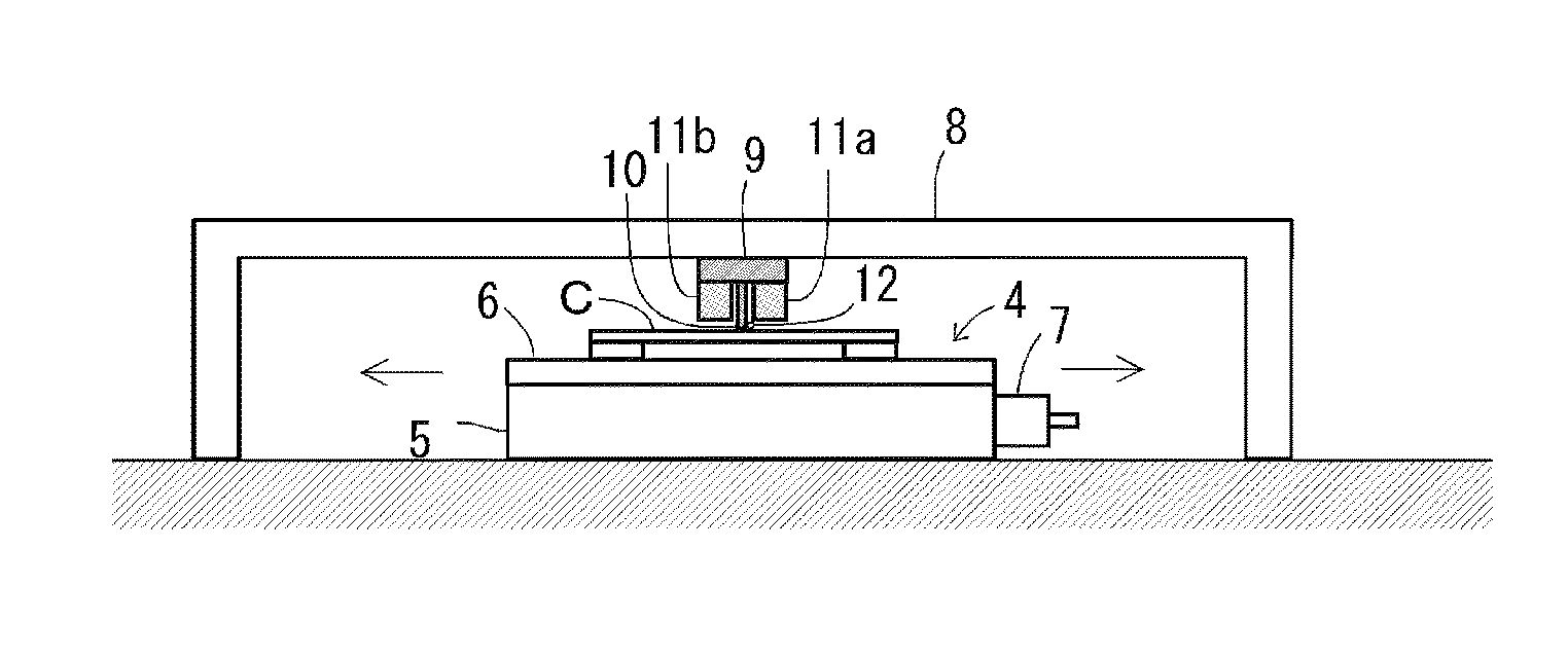
[0091]In Example 1-1, a gigantic colloidal single crystal was prepared from fine colloidal polycrystals by a zone melting process to be shown later.

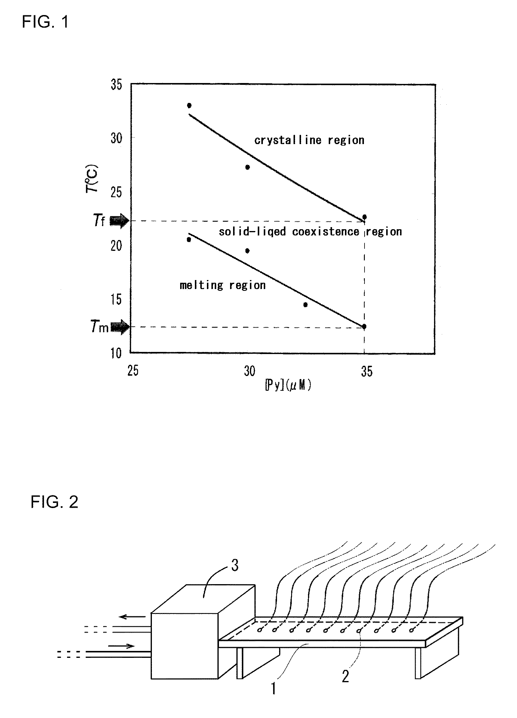
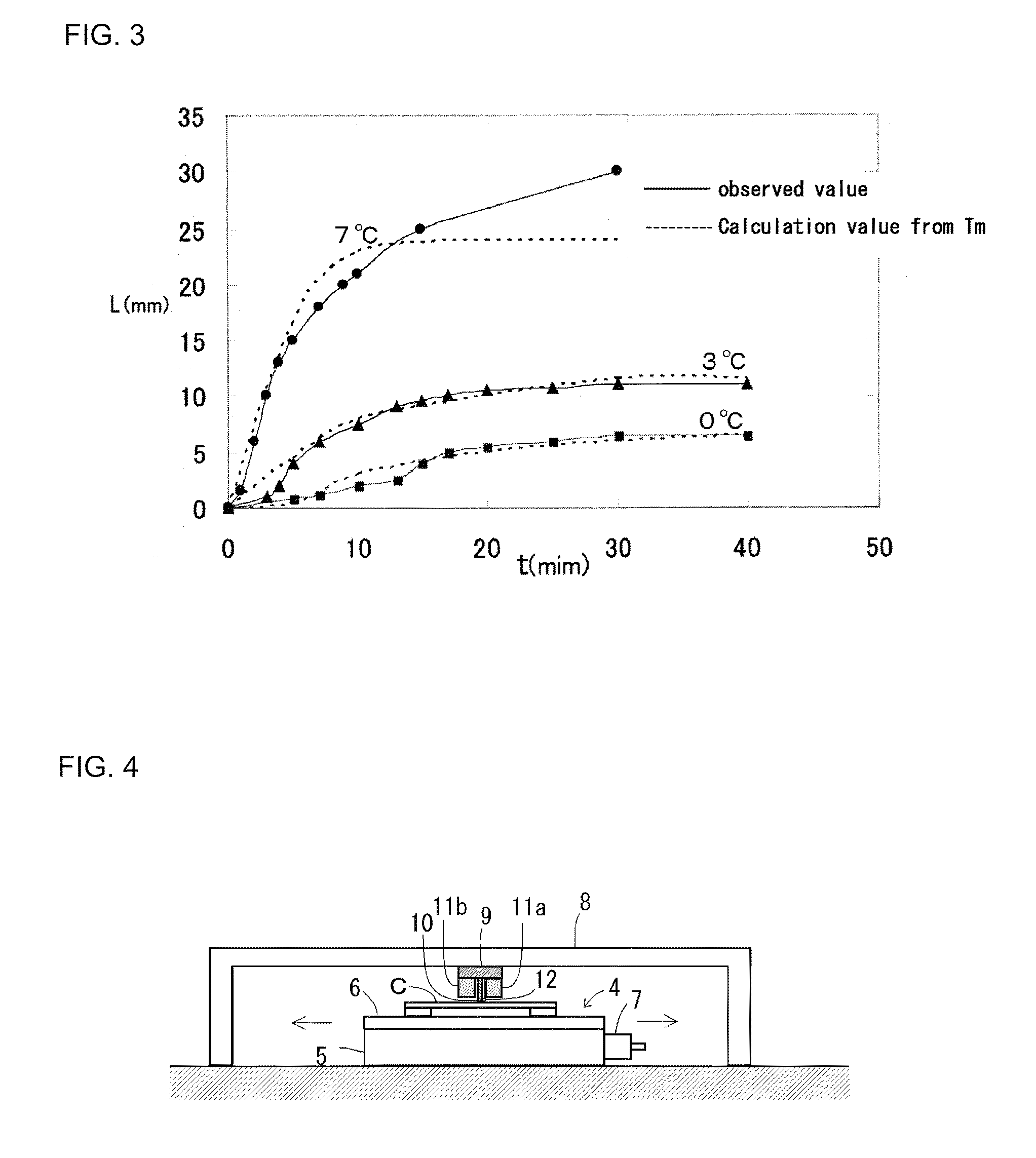
[0092]First, silica colloidal particles KE-W10 (diameter: 0.11±0.01 μm, specific gravity: 2.1) manufactured by Nippon Shokubai Co., Ltd. were purified using dialysis by a semipermeable membrane, and an ion-exchange process using an ion-exchange resin. A silica colloid from which ions were thus removed was adjusted so that a volume fraction (φ)=0.050 was set, and pyridine was added thereto so that a pyridine concentration was set to produce 50 μmol / L to produce a colloidal polycrystal dispersion. When the colloidal polycrystal dispersion was left at room temperature, fine colloidal polycrystals glitteringly shining were observed with the naked eye. The colloidal polycrystal dispersion was separately put into the quartz cell. The fine colloidal polycrystals were formed, and the colloidal polycrystal dispersion was then cooled. When a tempe...

examples 1-2 to 1-4

[0099]In Examples 1-2 to 1-4, colloidal crystals were prepared at the moving speed of the Peltier element 9 which is different from that in the case of Example 1-1 (that is, 18 mm / min in Example 1-2, 30 mm / min in Example 1-3, and 42 ram / min in Example 1-4). Other preparation conditions are the same as those in Example 1-1. The results are shown in FIG. 6. FIG. 6 shows that the larger a moving speed ν of a cooling portion (that is, a melting area of colloidal polycrystals) is, the smaller a crystal size is.

[0100]In the preparation of the colloidal crystals of Example 1-1 (that is, ν=2 mm / min), a surface temperature of a cell opposite to the Peltier element 9 was measured using an infrared type thermography device (TH6300 type manufactured by NEC / Avio Corporation). The results are shown in FIG. 7. FIG. 7A shows temperature distribution images of every 5 minutes. FIG. 7B shows a relation between a temperature and a position x (a distance from a left end of a cell) on a horizontal line ...

example 2-1

[0102]In Example 2-1, fluorescence polystyrene particles were used as imitation impurities, and an exclusion test of impurity particles by a zone melting process was conducted. Hereinafter, the test process will be described in detail.

[0103]That is, fluorescence polystyrene fine particles (particle diameter=100 nm) as model impurities were added to a dispersion liquid in which pyridine of 50 μmol / L was added to purified silica colloid (particle diameter=100 nm, particle concentration=5 vol %) so that a particle concentration=0.02 vol % was set. The colloidal polycrystal dispersion thus prepared was an assembly of microcrystals of 1 mm or less. The colloidal polycrystal dispersion was put into a quartz cell of 1×1×4.5 cm. The zone melting device used in Example 1-1 was used. Zone melting treatment was conducted by moving the Peltier element 9 leftward by about 3 cm from the right end of a cell at a speed / of 2 mm / min at 25° C. while controlling the Peltier element 9 so that the tip of...


PUM

PropertyMeasurementUnit
lengthaaaaaaaaaa
widthaaaaaaaaaa
moving speedaaaaaaaaaa

Abstract

Provided is a process for producing colloidal crystals from which a large single crystal reduced in lattice defects and unevenness can be easily produced at low cost without fail. The process for colloidal crystal production comprises: preparing a colloidal polycrystal dispersion in which colloidal crystals precipitate at a given temperature (preparation step); introducing into a vessel The colloidal polycrystal dispersion in the state of containing fine colloidal polycrystals precipitated (introduction step); and melting the colloidal polycrystals and then recrystallizing the molten polycrystals (recrystallization step). The crystals thus obtained have fewer lattice defects and less unevenness than the original polycrystals.

Description

TECHNICAL FIELD[0001]The present invention belongs to a colloidal technical field. In particular, the present invention relates to a process for producing colloidal crystals using a colloidal polycrystal dispersion crystallized by a change in temperature and to colloidal crystals produced using the process.BACKGROUND ART[0002]Colloid means a state where colloidal particles having a size of several nm to several μm are dispersed in a medium, and has a broad industrial application in fields such as paints and medical supplies.[0003]When a suitable condition is selected, the colloidal particles are regularly disposed in a colloidal dispersion and form a structure referred to as a “colloidal crystal”. There are two types of the colloidal crystal. The first type is a crystal formed on a condition that a particle volume fraction is about 0.5 (a concentration=50% by volume) or more in a colloidal system (hard sphere system) having no particular interaction between particles. This is simila...

Claims


Application Information

Patent Timeline
Patent Type & Authority Patents(United States)
IPC IPC(8): C30B7/14C01B33/14C01B33/157C01B33/18C30B5/00
CPCC30B5/00C01B33/14C01B33/157C01B33/18Y10T428/298
Inventor YAMANAKA, JUNPEISHINOHARA, MARIKOTOYOTAMA, AKIKOYOSHIZAWA, KOKIONDA, SACHIKOYONESE, MASAKATSUUCHIDA, FUMIO
Owner NAGOYA CITY UNIVERSITY
Learn More