System for diagnosing delta pressure sensor operation

Active Publication Date: 2005-02-01
CUMMINS INC
View PDF27 Cites 75 Cited by
  • Summary
  • Abstract
  • Description
  • Claims
  • Application Information

AI Technical Summary

Benefits of technology

[0006]The present invention may comprise one or more of the following features and combinations thereof. A system for diagnosing operation of a delta pressure sensor used with an internal combustion engine comprises an intake manifold and an exhaust manifold each operatively coupled to the engine, an EGR conduit fluidly coupled between the intake and exhaust manifolds, and a flow restriction mechanism disposed in-line with the EGR conduit, wherein the delta pressure sensor produces a delta pressure signal indicative of a pressure differential across the flow restriction mechanism. A control computer compares the delta pressure signal to a modeled delta pressure value modeled as a function of at least engine speed and one of engine load and engine output torque percentage, and diagnoses a fault state of the delta pressure sensor based on the comparison.
[0007]The flow restriction mechanism may be an EGR valve having an actuator responsive to an actuator signal to control exhaust gas flow through the EGR valve, wherein the control computer is configured to produce the actuator signal. Alternatively or additionally, the system may include the EGR valve and the flow restriction mechanism may be disposed in-line with the EGR conduit between the EGR valve and the intake manifold.
[0008]The system may further include an engine speed sensor producing an engine speed signal indicative of engine rotational speed, and the control computer may be configured to determine an engine load value as a function of engine fueling. The control computer may further be configured to determine the modeled delta pressure value as a function of the engine speed signal and the engine load value according to one predefined delta pressure model. Alternatively, the control computer may be configured to determine an engine output torque percentage, and to determine the modeled delta pressure value as a function of the engine speed signal and the engine output torque percentage according to another predefined delta pressure model. In either case, the control computer is operable to determine a residual value as a difference between the delta pressure signal and the modeled delta pressure value, and to diagnose the fault state of the delta pressure sensor based on the residual value. In this embodiment, the control computer may be configured to control the actuator signal to command the EGR valve to a predefined valve position prior to determining the modeled delta pressure value. The system may further include a turbocharger operatively coupled to the intake and exhaust manifolds, wherein the turbocharger has a variable geometry turbine (VGT) mechanism with an actuator responsive to an actuator signal to control a swallowing capacity or efficiency of the turbocharger, and in this embodiment the control computer may be additionally configured to control the actuator signal to command the VGT mechanism to a predefined VGT position prior to determining the modeled delta pressure value. The system in this embodiment may further include a memory having a delta pressure sensor diagnostic flag stored therein, and the control computer may further include a flag counter operable to increment a count value if the residual value exceeds a threshold residual value and to otherwise decrement the count value. The control computer may be operable to diagnose the fault state of the delt

Problems solved by technology

When combustion occurs in an environment with excess oxygen, peak combustion temperatures increase which leads to the formation of unwanted emissions, such as oxides of nitrogen (NOx).
This problem is aggravated through the use of

Method used


Image

  • System for diagnosing delta pressure sensor operation
  • System for diagnosing delta pressure sensor operation
  • System for diagnosing delta pressure sensor operation

Examples


Embodiment Construction

class="d_n">[0020]FIG. 10 is a block diagram of one illustrative embodiment of the diagnostic conditions evaluation logic block of FIG. 9.

[0021]FIG. 11 is a block diagram of one illustrative embodiment of the delta pressure diagnostic logic block of FIG. 9.

[0022]FIG. 12 is a plot of intake manifold pressure vs. exhaust manifold pressure illustrating one embodiment of the ΔP rationality diagnostic block of FIG. 2.

DESCRIPTION OF THE ILLUSTRATIVE EMBODIMENTS

[0023]For the purpose of promoting an understanding of the principles of this disclosure, reference will now be made to one or more embodiments illustrated in the drawings and specific language will be used to describe the same. It will nevertheless be understood that no limitation of the scope of the disclosure is thereby intended.

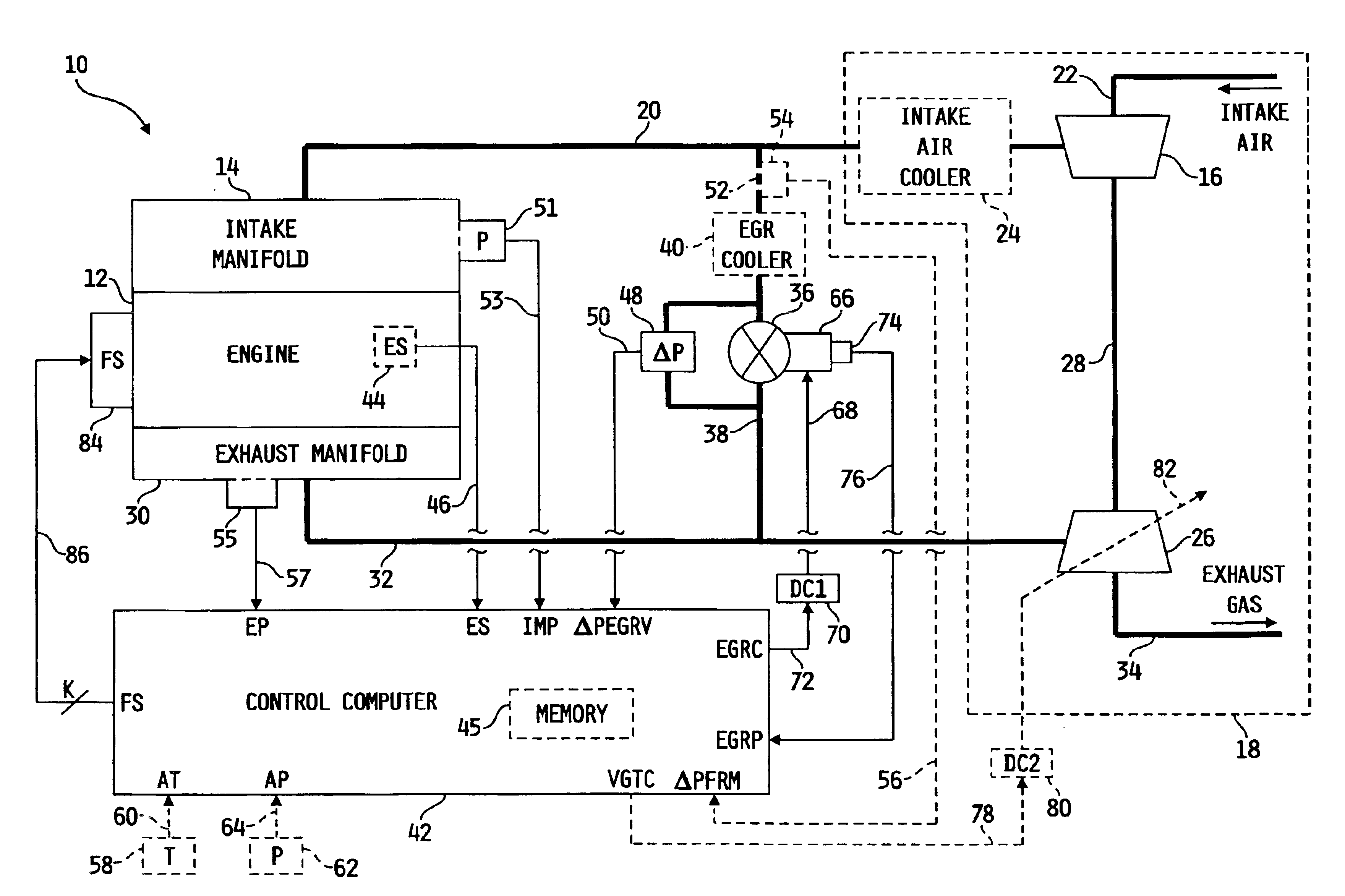
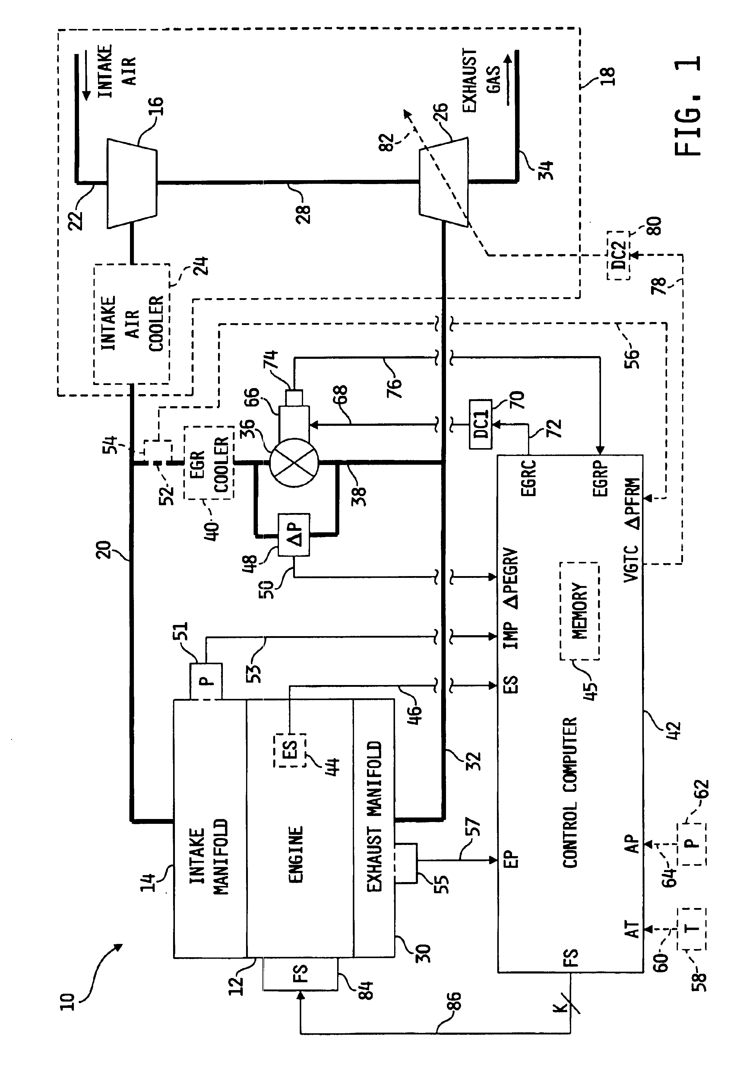
[0024]Referring now to FIG. 1, a diagram of one illustrative embodiment of a system 10 for diagnosing the operation of a delta pressure sensor used with an internal combustion engine is shown. System 10 i...


PUM


Abstract

A system for diagnosing operation of a delta pressure sensor used with an internal combustion engine comprises an intake manifold and an exhaust manifold each operatively coupled to the engine, an EGR conduit fluidly coupled between the intake and exhaust manifolds, and a flow restriction mechanism disposed in-line with the EGR conduit, wherein the delta pressure sensor produces a delta pressure signal indicative of a pressure differential across the flow restriction mechanism. A control computer compares the delta pressure signal to a modeled delta pressure value modeled as a function of at least engine speed and one of engine load and engine output torque percentage, and diagnoses a fault state of the delta pressure sensor based on the comparison.

Description

FIELD OF THE DISCLOSURE[0002]The present invention relates generally to systems for monitoring the operation of a delta pressure sensor used with an internal combustion engine, and more specifically to such systems for diagnosing faults or failure conditions associated delta pressure sensor operation.BACKGROUND OF THE DISCLOSURE[0003]When combustion occurs in an environment with excess oxygen, peak combustion temperatures increase which leads to the formation of unwanted emissions, such as oxides of nitrogen (NOx). This problem is aggravated through the use of turbocharger machinery operable to increase the mass of fresh air flow, and hence increase the concentrations of oxygen and nitrogen present in the combustion chamber when temperatures are high during or after the combustion event.[0004]One known technique for reducing unwanted emissions such as NOx involves introducing chemically inert gases into the fresh air flow stream for subsequent combustion. By thusly reducing the oxyg...

Claims


Application Information

Patent Timeline
IPC IPC(8): F02D21/00F02D41/22F02D21/08F02M25/07G01L27/00G01F1/36G01F9/00G01F9/02G01F15/00G01F25/00
CPCF02D41/0055F02M25/0702F02M25/0754G01L27/007G01F9/001G01F9/023G01F15/005G01F25/0007G01F1/36F02D41/222F02M25/0707F02M25/0727Y02T10/47F02M26/05F02M26/49F02M26/23F02M26/47Y02T10/40G01F25/10
Inventor WANG, YUE YUNRAUZNITZ, PETERBROOKS, MARTIN T.
Owner CUMMINS INC
Why Eureka
Try Eureka