Data fusion of stationary array sensor and scanning sensor measurements

a technology of stationary array sensor and scanning sensor, which is applied in the direction of special data processing applications, electric/magnetic measuring arrangements, digital computer details, etc., can solve the problems of high cost, inability to include sensors with a high degree of precision, and the scan rate of scanning sensor is too slow to adequately address the dynamics of cross-directional variations of process properties being controlled, etc., to achieve simple, computational structure, and improve accuracy

Inactive Publication Date: 2005-02-01
HONEYWELL INT INC
View PDF11 Cites 25 Cited by
  • Summary
  • Abstract
  • Description
  • Claims
  • Application Information

AI Technical Summary

Benefits of technology

The present invention is directed to improving the accuracy with which a stationary array sensor provides cross directional measurements by periodically providing an offset compensation to the stationary array sensor using the output of a scanning sensor associated with the same manufacturing process. Exemplary embodiments correlate outputs from the stationary sensor array and the scanning array using a data reconciliation process. For example, a practical, real time data reconciliation of measurements from the scanning sensor and measurements from the stationary array sensor is achieved using a bank of Kalman filters to correlate outputs from the two sensors for each cross-directional measurement zone, wherein each filter possesses a relatively simple, computational structure. The Kalman filters can fuse the outputs from the stationary array sensor and the scanning sensor to track, and compensate, drift of the stationary array sensor.

Problems solved by technology

Because the profile data associated with a scanning sensor is available only once per scan cycle, the scanning sensor's scan rate can be too slow to adequately address the dynamics of cross directional variations of the process property being controlled.
Although stationary array sensors avoid the need of a cross directional scan using motion of a single sensor back and forth over the moving paper sheet, the requirement that the stationary array sensor includes a plurality of individual sensors can render it quite expensive.
This need for a large number of individual sensors in the stationary sensor array renders it cost prohibitive to include sensors having a high degree of precision.
That is, to provide a stationary sensor array that can achieve measurements with an accuracy that approaches the accuracy of measurements achieved with a scanning sensor, expensive individual sensors must be used.
Again, in these circumstances, the stationary sensor array is typically configured with sensors that render the array cost competitive with scanning sensors used at other locations in the process.
In addition to the use of less expensive, less accurate sensors in stationary sensor arrays, another factor which detracts from the quality of the measurements they provide is their susceptibility to drift.
Such a recalibration cannot be easily achieved with stationary sensor arrays, wherein each of the sensors is fixed in position.

Method used


Image

  • Data fusion of stationary array sensor and scanning sensor measurements
  • Data fusion of stationary array sensor and scanning sensor measurements
  • Data fusion of stationary array sensor and scanning sensor measurements

Examples


Embodiment Construction

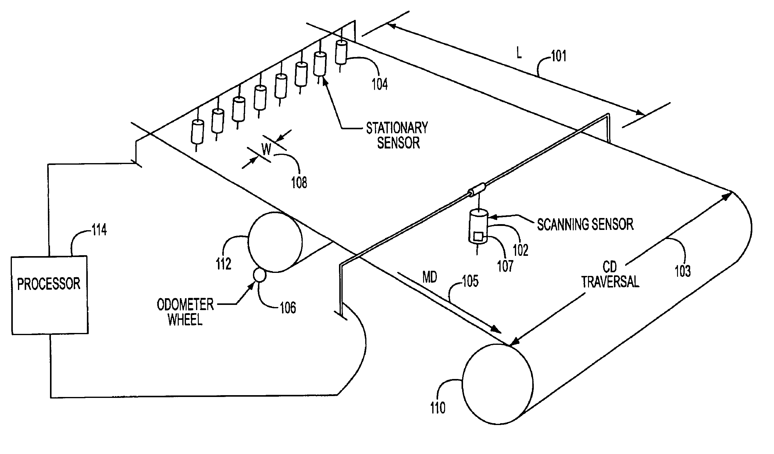
The present invention relates to a measurement system, and associated method, which can be applied to any manufacturing process. For example, FIG. 1 illustrates a measurement system for use with a paper production process wherein, according to exemplary embodiments of the present invention, data measurements obtained from plural locations using different types of sensors are fused.

Referring to FIG. 1, a measurement system is illustrated for measuring a variable of at least one property of a product, such as a paper web, and including at least one stationary sensor and one scanning sensor. A stationary sensor shown in FIG. 1 can be a stationary sensor array 104 provided at a first location in the manufacturing process to produce a first array of measurement outputs.

FIG. 1 also illustrates measuring the variable of the product and / or process with a scanning sensor such as scanning sensor 102. The scanning sensor 102 is located at a second location in the manufacturing process to produ...


PUM


Abstract

The present invention is directed to improving the accuracy with which a stationary array sensor provides cross directional measurements by providing an offset compensation to the stationary array sensor using the output of a scanning sensor associated with the manufacturing process. Exemplary embodiments correlate outputs from the stationary sensor array and the scanning array using a data reconciliation process. For example, a practical, real time data reconciliation of measurements from the scanning sensor and measurements from the stationary array sensor is achieved by computing offsets using a bank of Kalman filters to correlate outputs from the two sensors for each measurement zone, wherein each filter possesses a relatively simple computational structure. The Kalman filters can fuse the outputs from the stationary array sensor and the scanning sensor to track, and compensate, drift of the stationary array sensor.

Description

BACKGROUND OF THE INVENTION1. Field of the InventionThis invention generally addresses the cross directional control of a process, such as a paper manufacturing process. The invention can improve the accuracy of a stationary array sensor employed for cross directional control by fusing the sensor output with the output of a scanning gauge, or sensor, using a bank of filters such as Kalman filters, where each filter in the bank has a simple computational structure.2. Background InformationCross directional (CD) control of processes, such as paper manufacturing processes, is known. For example, U.S. Pat. No. 4,903,528 entitled “System and Process For Detecting Properties Of Traveling Sheets In Cross Direction”, U.S. Pat. No. 4,965,736 entitled “Cross-Directional Control Of Sheetmaking Systems” and U.S. Pat. No. 5,121,332 entitled “Control System For Sheetmaking”, the disclosures of which are all hereby incorporated by reference, are directed to cross directional control using a scanni...

Claims


Application Information

Patent Timeline
Patent Type & Authority Patents(United States)
IPC IPC(8): D21G9/00
CPCD21G9/0054
Inventor IGNAGNI, MARIOGORINEVSKY, DIMITRY
Owner HONEYWELL INT INC
Why Eureka
Try Eureka