

Apparatus for maintaining freshness
- Summary
- Abstract
- Description
- Claims
- Application Information
AI Technical Summary
Benefits of technology
Problems solved by technology
Method used
Image


Examples
first embodiment
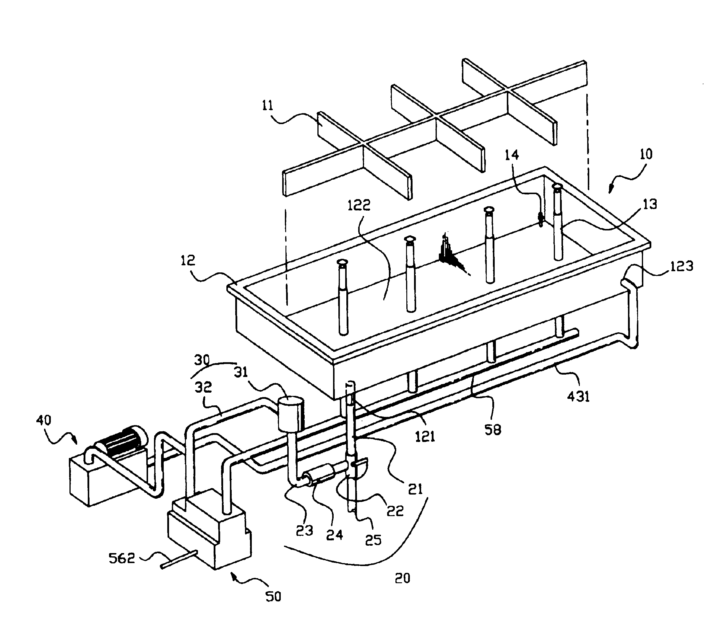
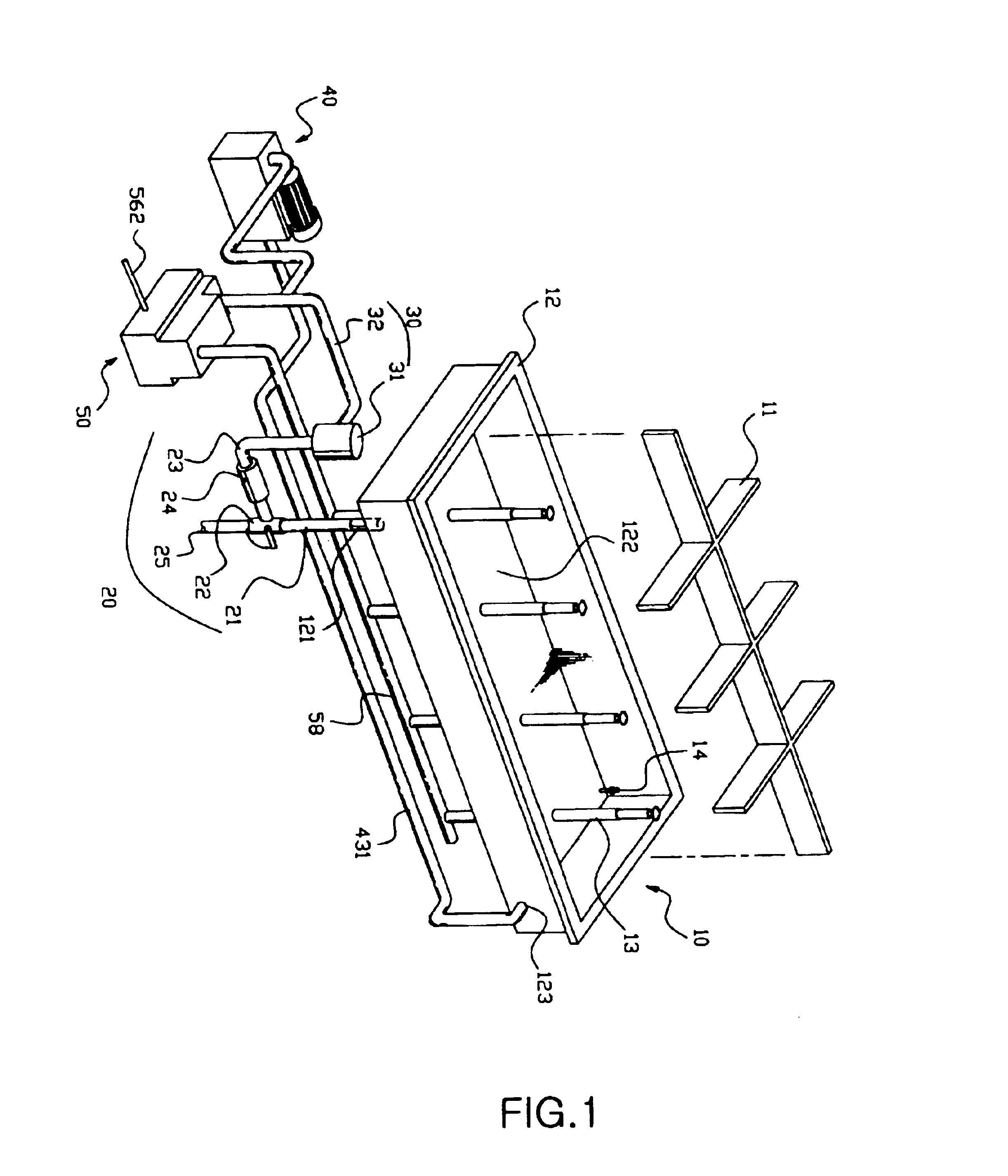
When one desires to keep items, such as flowers, foodstuffs, fruit, and others, fresh using the apparatus according to the present invention, the items are stored in the water storage unit 10 to be supported by the support unit 11. Next, in response to a signal output from the control unit 60, the water supply pump 24 and the thermoelement or heat exchanger of the cooling unit 40 are operated and the vibrator 54 is vibrated by the high-frequency wave generator 55. At this time, the water is fed from the water storage unit 10 to the filtering unit 30. After passing through the filtering unit 30, the water fed to the cooling unit 40 is cooled to the predetermined temperature of 2˜4° C., and the water fed to the humidifying unit 50 is atomized by the vibrator 54. Thereafter, the water is returned to the water storage unit 10.
In a detailed description, the water is fed to the filtering unit 30 by the operation of the water supply pump 24, and subsequently the filtered water is fed throu...
third embodiment
FIG. 7 is a perspective view showing a water storage unit included in a freshness maintaining apparatus, according to the present invention. FIG. 8 is a sectional view showing an interior structure of the water storage unit shown in FIG. 7. When one desires to store two or more items using the apparatus of the present invention, the shape of the support unit which is mounted to the water storage unit 10 may be changed as shown in FIGS. 7 and 8. For example, when one desires to store flowers and vegetables, the stems of the flowers soak in water contained in the water storage unit 10. In this case, the water stored in the water storage unit 10 is used to produce cool and humid air. However, the water stored in the water storage unit 10 is poor in quality. Thus, an additional water container 11c may be provided to store the flowers. That is, as shown in FIGS. 7 and 8, a seating hole 111b is formed at a center of the support unit 11b which has the net shape so that the vegetables are p...
fourth embodiment
FIG. 9 is a sectional view showing a freshness maintaining apparatus, according to the present invention. As shown in FIG. 9, the apparatus may be provided with a plurality of water storage units which are connected to each other. FIG. 9 shows the apparatus provided with two water storage units. As shown in FIG. 9, the apparatus includes first and second water storage units 10d and 10e, each of which is provided with the support unit and contains water therein. Each of the first and second water storage units 10d and 10e is connected at a lower end thereof to a cooling unit 40 and a humidifying unit 50. A humidifying pipe 13 is mounted to each of the first and second water storage units 10d and 10e to be connected to a distributing pipe 58 of the humidifying unit 50. Further, a connection hole 123 is provided at a predetermined position of each of the first and second water storage units 10d and 10e to be connected to a cool water supply pipe 531.
The operation of the apparatus const...
PUM
 Abstract
Description
Claims
Application Information