Perforating gun

a perforating gun and gun body technology, applied in the field of perforating guns, can solve the problems of time-consuming and complicated assembly process of parts, and achieve the effect of increasing mechanical strength

a perforating gun and gun body technology, applied in the field of perforating guns, can solve the problems of time-consuming and complicated assembly process of parts, and achieve the effect of increasing mechanical strength

US6851471B2Inactive Publication Date: 2005-02-08HALLIBURTON ENERGY SERVICES INC

Image

  • Perforating gun
  • Perforating gun
  • Perforating gun

Examples


Embodiment Construction

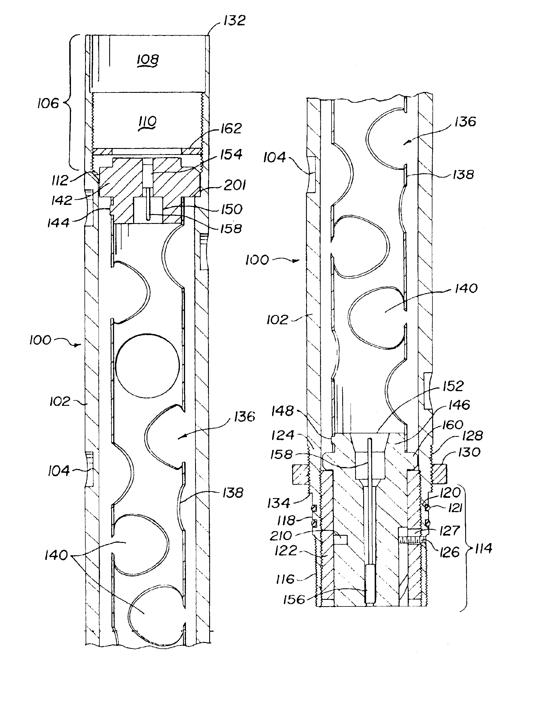
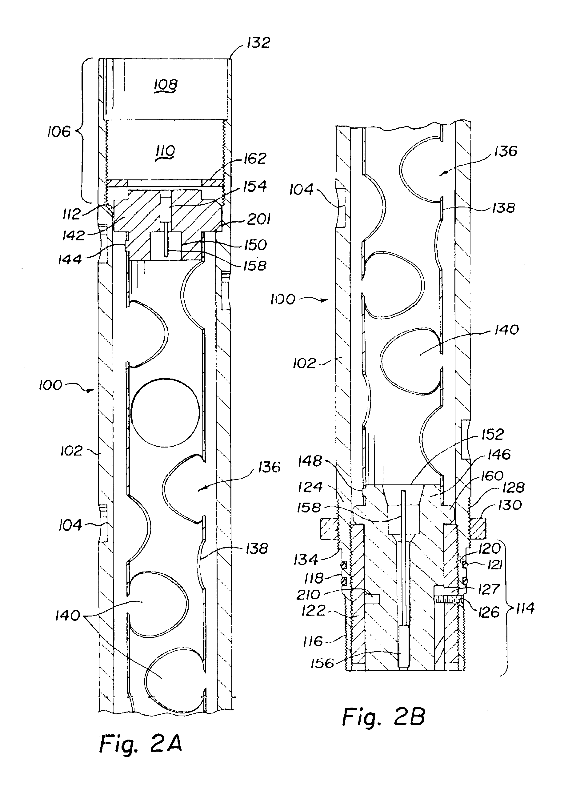
For purposes of describing the present invention the relative location of various parts will be referred to as “upper”, “lower”, “above”, and “below”. These terms are intended to describe the relative position of a perforating gun in the vertical position normally used for assembling the gun into or as part of a drill string or work string for lowering into a borehole. Boreholes are normally essentially vertical at their surface location. Work strings and drill strings are normally connected together joint by joint or section by section at the borehole surface location as they are lowered into the borehole. While perforating guns are sometimes lowered into a borehole on a string of drill pipe, it is understood that perforating gun assemblies are not designed to withstand the torque normally encountered during drilling operations and would not be present during drilling operations. These terms are used for convenience in describing the invention and are not intended to be limiting. A...


PUM


Abstract

A perforating gun assembly useful in hydrocarbon well completion. The gun is assembled in a carrier made from straight walled tubing as a primary structural member with complementary male and female threads cut into opposite ends so that gun assemblies may be directly connected together. The male coupling includes a reinforcing sleeve threaded into an internal thread. An alignment pin is positioned in the carrier extending through the reinforcing ring and into the interior of the carrier. A charge assembly includes a charge holder tube with upper and lower alignment fixtures. The lower alignment fixture includes an alignment slot for mating with the alignment pin and a shoulder for supporting the charge assembly on the sleeve. The upper alignment fixture has an alignment pin for mating with an alignment slot in the carrier. A retainer ring may be threaded into the upper female threads to prevent removal of the charge assembly from the carrier.

Description

CROSS-REFERENCE TO RELATED APPLICATIONSNone.STATEMENT REGARDING FEDERALLY SPONSORED RESEARCH OR DEVELOPMENTNot applicable.REFERENCE TO A MICROFICHE APPENDIXNot applicable.FIELD OF THE INVENTIONThe present invention relates to perforating guns for use in hydrocarbon producing wells and more particularly to a perforating gun assembly made from straight wall tubing, having male and female couplings on opposite ends and a simple charge holder assembly.BACKGROUND OF THE INVENTIONThe completion of oil and gas wells by gun perforating is well known in the art. A work string including one or more perforating guns is lowered into a well casing cemented into the well bore. The perforating guns are positioned adjacent to the formation to be perforated. The perforating guns are fired to penetrate the casing and cement and form perforations into the producing formation for recovery of the desired fluids. These perforating guns typically utilize shaped charges to form the perforations.Perforating...

Claims


Application Information

Patent Timeline
08 Feb 2005
Publication
US6851471B2
IPC
E21B17/02; E21B43/117; E21B17/042; E21B43/11; E21B43/119
CPC
E21B17/042; E21B43/119; E21B43/117
Inventors
BARLOW, DARREN R.; CROWDIS, DENNIS R.