Coupled circulation tube for ball screw unit

a technology of circulation tube and ball screw, which is applied in the direction of bends, gearing, hoisting equipment, etc., can solve the problems of power loss and apparatus operation damage, and achieve the effects of reducing production cost, improving mechanical toughness, and simplifying fabrication

Inactive Publication Date: 2005-02-08
HIWIN TECH
View PDF15 Cites 37 Cited by
  • Summary
  • Abstract
  • Description
  • Claims
  • Application Information

AI Technical Summary

Benefits of technology

It is an object of the present invention to provide a coupled circulation tube for a ball screw unit in which the circulation tube is symmetrically coupled with two half arcuate elbow tubes like an object and its reflected image of a plane mirror so as to simplify the fabrication, improve the mechanical toughness, and cut down the production cost.
It is a further object of the present invention that by such a coupled circulation tube the rolling balls are provided with an outer circulation pathway to smoothly and snugly travel around.
For achieving such objects, the coupled circulation tube is formed on the planar surface at one side of the ball screw bearing each tube jointing to two circulation holes. Each circulation tube is coupled of two symmetrical metallic half tubes by a plurality of recessed grooves and flanges interposedly arrayed one after another longitudinally along the wall of each half tube thereby coupling into a resultant U shaped arcuate elbow tube for ball circulation such that it is firmly constructed with a desired toughness free from loosening, cracking or deforming by constant collision and abrasion of the rolling balls.

Problems solved by technology

As the above described U shape elbow tube is parallelly coupled with two half pieces, it is subjected to inevitable and constant impact and collision of balls rolling inside for a long time ultimately resulting in a fatal damage to the operation of the apparatus due to metallic fatigue and scars produced by collision and abrasion of the balls on the inner surface of the circulation tube.
A circulation tube engaged with two half tubes always has a weakness of cracking at the bonding seam so that the basic requirement to assure a certain toughness is beyond one's power.

Method used


Image

  • Coupled circulation tube for ball screw unit
  • Coupled circulation tube for ball screw unit
  • Coupled circulation tube for ball screw unit

Examples


Embodiment Construction

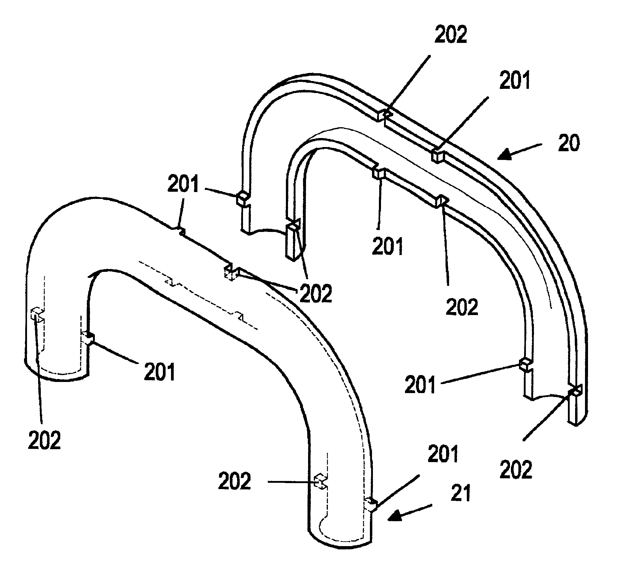
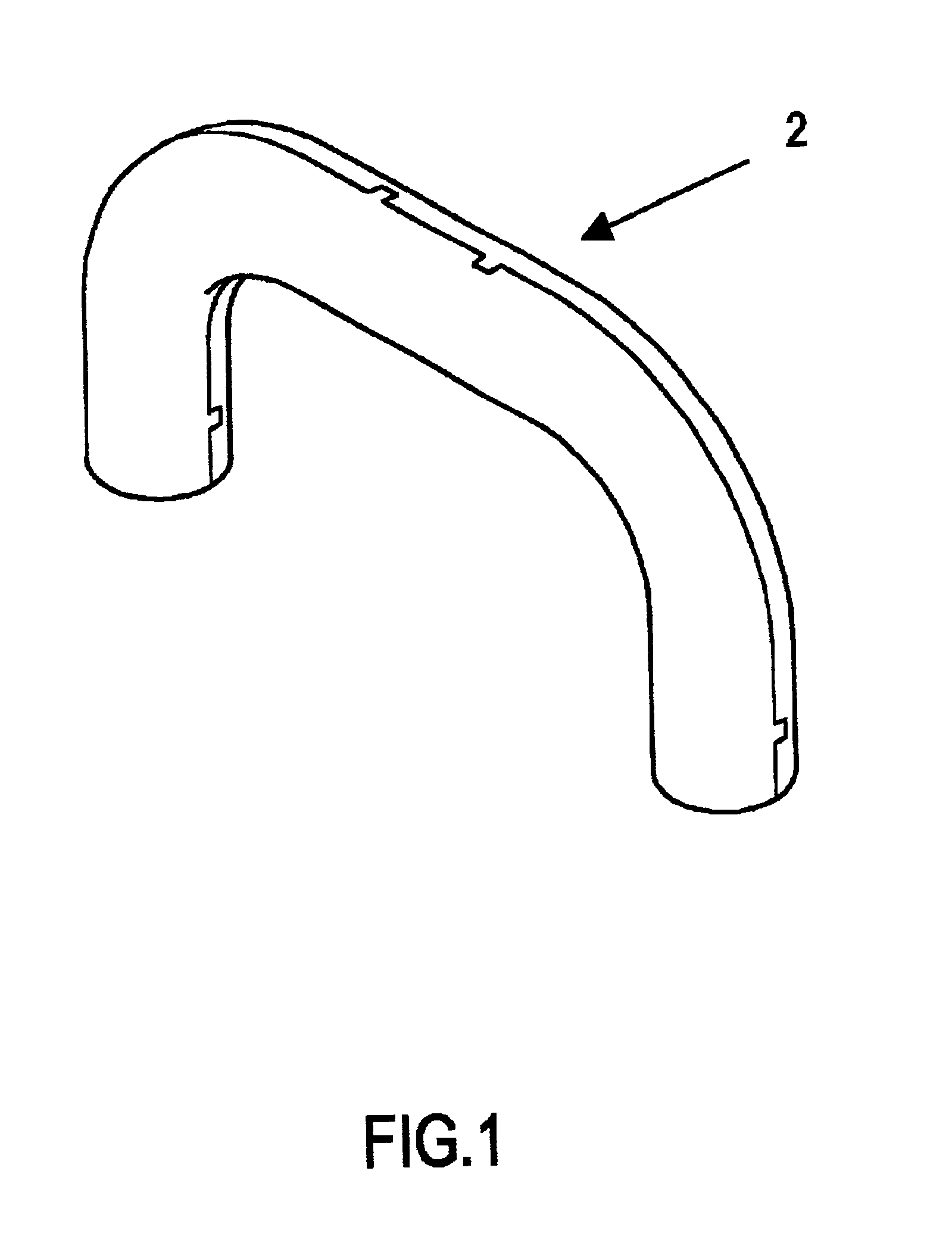
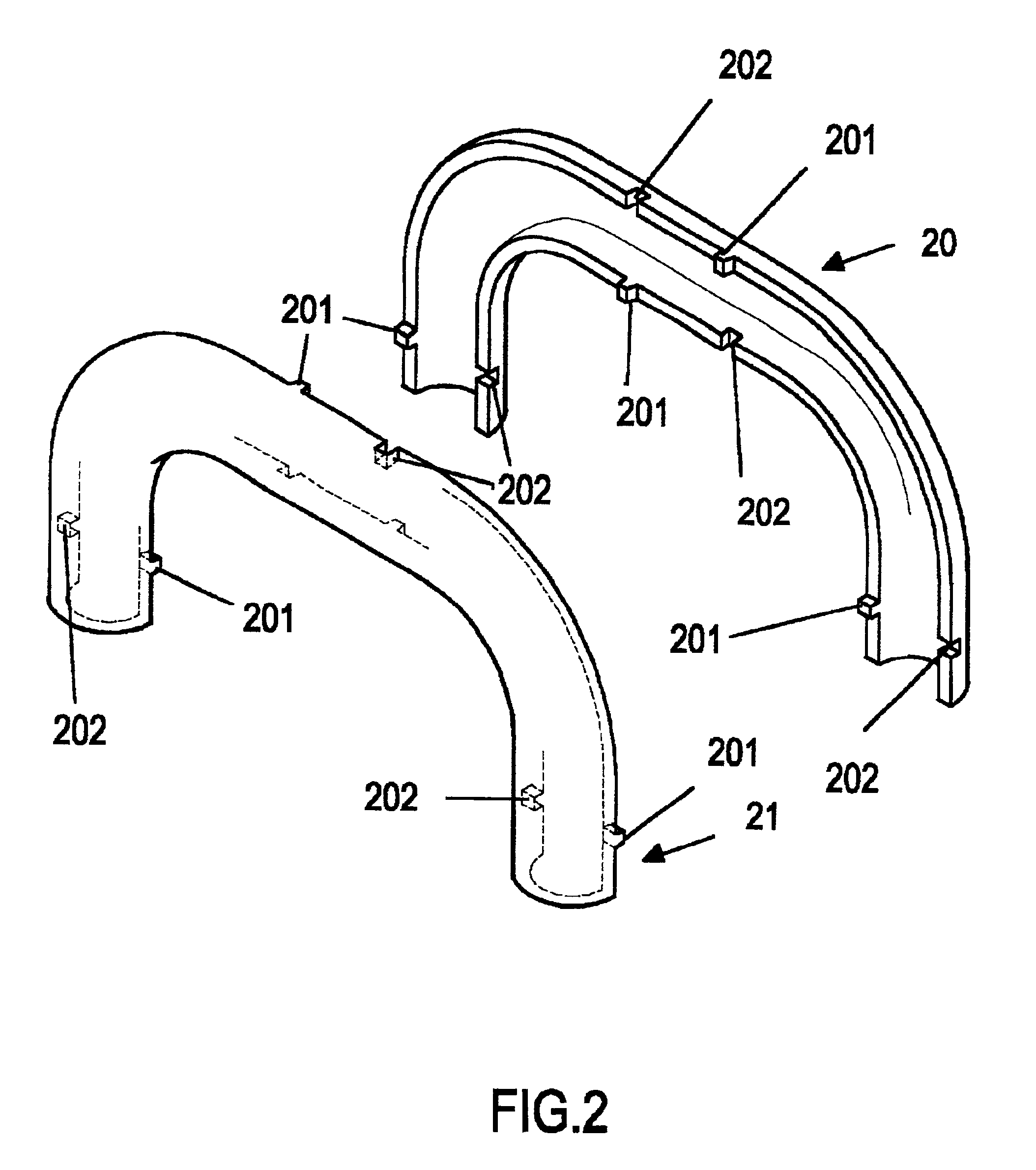
Referring to FIG. 1 together with FIG. 2, as it is clearly shown in FIG. 2, the arcuate elbow tube 2 is composed of a first half elbow tube 20 and a second half elbow tube 21 wherein both component tubes 20 and 21 being respectively made integrally in one piece of a metallic material and are symmetrically facing to each other like an object and its image reflected by a plane mirror.

Referring to FIG. 3, there are a plurality of flanges 201 and recessed grooves 202 interposedly arrayed one after another along the wall of each half tube to be coupled into a resultant U shaped arcuate elbow tube 2 as shown in FIGS. 1 and 4, and then engagement therebetween is further enhanced by welding. Besides, the arrayed flanges 201 and grooves 202 may be formed into a swallow-tailed configuration.

Referring to FIG. 5 together with FIG. 6, as shown in FIG. 6, there is one of the coupled arcuate elbow tube 2 fitted to a Pair of circulation holes 10, 11 opened on the upper side planar surface of the ba...


PUM


Abstract

A coupled circulation tube for a ball screw unit. The tube is formed on a planar surface at one side of the ball screw bearing, each tube joined to two circulation holes. Each circulation tube is formed by coupling two symmetrical rigid metallic half tubes at recessed grooves and flanges interposedly arrayed one after another longitudinally along the wall of each half tube to form a resultant U shaped arcuate elbow tube for ball circulation such that it is firmly constructed with a desired toughness free from loosening, cracking or deforming by constant collision and abrasion of the rolling balls.

Description

BACKGROUND OF THE INVENTION1. Field of the InventionThe present invention relates to a coupled circulation tube for ball screw unit, in particular, to a circulation tube symmetrically coupled with two half arcuate elbow tubes for ball screw unit so as to simplify the molding die, increase the mechanical toughness, and cut down the production cost.2. Description of the Prior ArtIn a conventional arcuate elbow tube for a ball screw unit, it is formed of two pieces of a first half arcuate elbow tube and a second half arcuate elbow tube parallelly simple contacted together to configure into a hollow snugly curved U shape tube for the rolling balls to circulate smoothly therein.As the above described U shape elbow tube is parallelly coupled with two half pieces, it is subjected to inevitable and constant impact and collision of balls rolling inside for a long time ultimately resulting in a fatal damage to the operation of the apparatus due to metallic fatigue and scars produced by collis...

Claims


Application Information

Patent Timeline
Patent Type & Authority Patents(United States)
IPC IPC(8): F16H25/22
CPCF16H25/2214Y10T74/19772Y10T74/19749Y10T74/19767
Inventor CHIU, YUEH-LINGYANG, PAUL
Owner HIWIN TECH
Why Eureka
Try Eureka