Rotatable bit having a resilient retainer sleeve with clearance

a technology of a retainer sleeve and a resilient sleeve, which is applied in the field of rotatable bits, can solve the problems of obstructing the compression reducing the diameter of the retainer ring, and building up of dirt and other debris in the bore of the holder

Inactive Publication Date: 2005-02-08
KENNAMETAL INC
View PDF56 Cites 146 Cited by
  • Summary
  • Abstract
  • Description
  • Claims
  • Application Information

AI Technical Summary

Benefits of technology

In another form thereof, the invention is an auger drilling bit body retainer sleeve for use on a rotatable drilling bit body wherein the drilling bit body further includes a reduced diameter portion. The retainer sleeve comprises a retainer sleeve body that has a thickness and presents an exterior surface that is generally smooth. The retainer sleeve body is carried by the drilling bit body within the reduced diameter portion. The retainer sleeve body has a first axial length. The reduced diameter portion has a first diameter. The first axial length of the retainer sleeve body is less than the first diameter of the reduced diameter portion.
In yet another form thereof, the invention is a drilling bit that comprises a drilling bit body that has an ...

Problems solved by technology

During the drilling operation, there is a build up of dirt and other debris in the bore of the holder.
The presence of this debris between the resilient retainer ring and the reduced diameter portion of the drilling bit obstructs the compression of the retainer ring.
This makes it difficult for the retainer ring to compress when the operator strikes the rear end of the drilling bit.
As can be appreciated, it can sometimes take a lot of ...

Method used


Image

  • Rotatable bit having a resilient retainer sleeve with clearance
  • Rotatable bit having a resilient retainer sleeve with clearance
  • Rotatable bit having a resilient retainer sleeve with clearance

Examples


Embodiment Construction

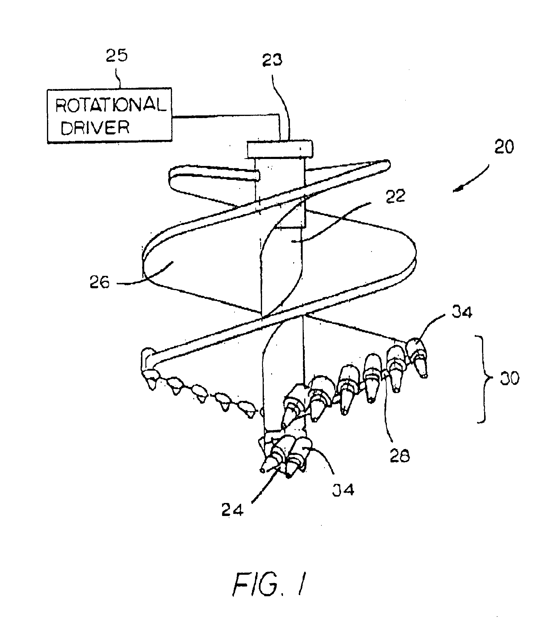
Referring to the drawings, FIG. 1 illustrates a drilling apparatus (an auger drill for engaging a substrate) that is a bullet tooth rock auger and is generally designated as 20. Although the specific embodiment illustrated herein is a drilling apparatus, it should be appreciated that the invention may have application to other types of assemblies that engage a substrate. Auger 20 includes a central auger shaft 22 that has an upper end 23 and a distal (or lower) end 24. In operation, the distal end 24 of the auger 20 is in contact with the substrate that is being (or to be) drilled. The auger 20 is operatively connected at the upper end 23 of the auger shaft 22 to a rotational driver (shown in schematic) 25. The rotational driver 25 comprises a conventional rotational driver. The rotational driver 25 provides rotational movement to the drilling apparatus 20 so as to allow it to perform its drilling function.

The drilling apparatus 20 also includes a helical auger flight 26 on the auge...


PUM


Abstract

A drilling bit for use in conjunction with a holder that has a bore wherein the drilling bit has a drilling bit body that has an axial forward end and an axial rearward end. The drilling bit body further includes a reduced diameter portion adjacent to the axial rearward end thereof so as to define a reduced diameter surface. A hard insert is affixed to the drilling bit body at the axial forward end thereof. A resilient retainer sleeve has a first thickness and presents an interior surface. The retainer sleeve is carried by the drilling bit body within the reduced diameter portion. The resilient retainer sleeve is in an expanded condition when the drilling bit is not within the bore of the holder and the resilient retainer sleeve is in a compressed condition when the drilling bit being within the bore of the holder. The clearance between the reduced diameter surface of the drilling bit body and the interior surface of the resilient retainer sleeve when the resilient retainer sleeve is in its compressed condition is at least as great as the thickness of the resilient retainer sleeve.

Description

FIELD OF THE INVENTIONThe present invention pertains to a rotatable bit that in operation rotates about its central longitudinal axis so as to engage a substrate such as, for example, earth strata. More specifically, the invention pertains to such a rotatable bit that includes a resilient retainer sleeve wherein the rotatable bit is held via the resilient retainer sleeve within the bore of a holder that is a part of an assembly used to engage the earth strata.BACKGROUND OF THE INVENTIONThere are a number of different types of circumstances (or applications) wherein a rotatable bit is used to engage a substrate (e.g., earth strata). These different circumstances use assemblies such as a rotary drum, a cutting chain, a scrapper (or scarifier) blade, and drilling equipment (e.g., augers). Examples of these applications include underground mining, surface mining, dredging, construction road planning, trenching, road grading, and snow / ice removal.In some of the above applications, the ro...

Claims


Application Information

Patent Timeline
IPC IPC(8): E21C35/00E21C35/197E21B10/44E21B10/00
CPCE21C35/197E21B10/44
Inventor BEACH, WAYNE H.
Owner KENNAMETAL INC
Why Eureka
Try Eureka