Method for measuring and assembling transceiver optical sub-assembly

a transceiver and optical sub-assembly technology, applied in the direction of optical elements, angle measurement, instruments, etc., can solve the problems of inability to accurately and accurately measure inability to provide effective and precise measurement, direct adverse effects on the quality of finished osa, etc., to optimize the transmission bandwidth of multi-mode fiber, reduce mode dispersion, and optimize the effect of fiber coupling mode distribution

Inactive Publication Date: 2005-02-08
E PIN OPTICAL IND
View PDF8 Cites 21 Cited by
  • Summary
  • Abstract
  • Description
  • Claims
  • Application Information

AI Technical Summary

Benefits of technology

Another object of the present invention is to provide a method for measuring and assembling a transceiver optical sub-assembly, in which a light spot presented on the fiber coupling plane by a laser beam emitted from the functional element through the lens, or an image of a light-emitting area or a receiving area of the functional element presented on the fiber coupling plane via the lens is directly used as an object

Problems solved by technology

Since it is highly difficult to make the mold for forming the housing A2, it is uneasy to control the quality of an injection-molded finished product of the housing A2.
Since the conventional adjustment and measurement operation adjusts the position of the functional element is based on the fiber coupling efficiency, it fails to optimize the fiber transmission bandwidth, and accordingly, could not provide effective and precise measurement to directly adversely affect the quality of the finished OSA A1.3. The above-mentioned conventional measuring method for adjusting the position of the functional element based on the fiber coupling efficiency further includes many

Method used


Image

  • Method for measuring and assembling transceiver optical sub-assembly
  • Method for measuring and assembling transceiver optical sub-assembly
  • Method for measuring and assembling transceiver optical sub-assembly

Examples


Embodiment Construction

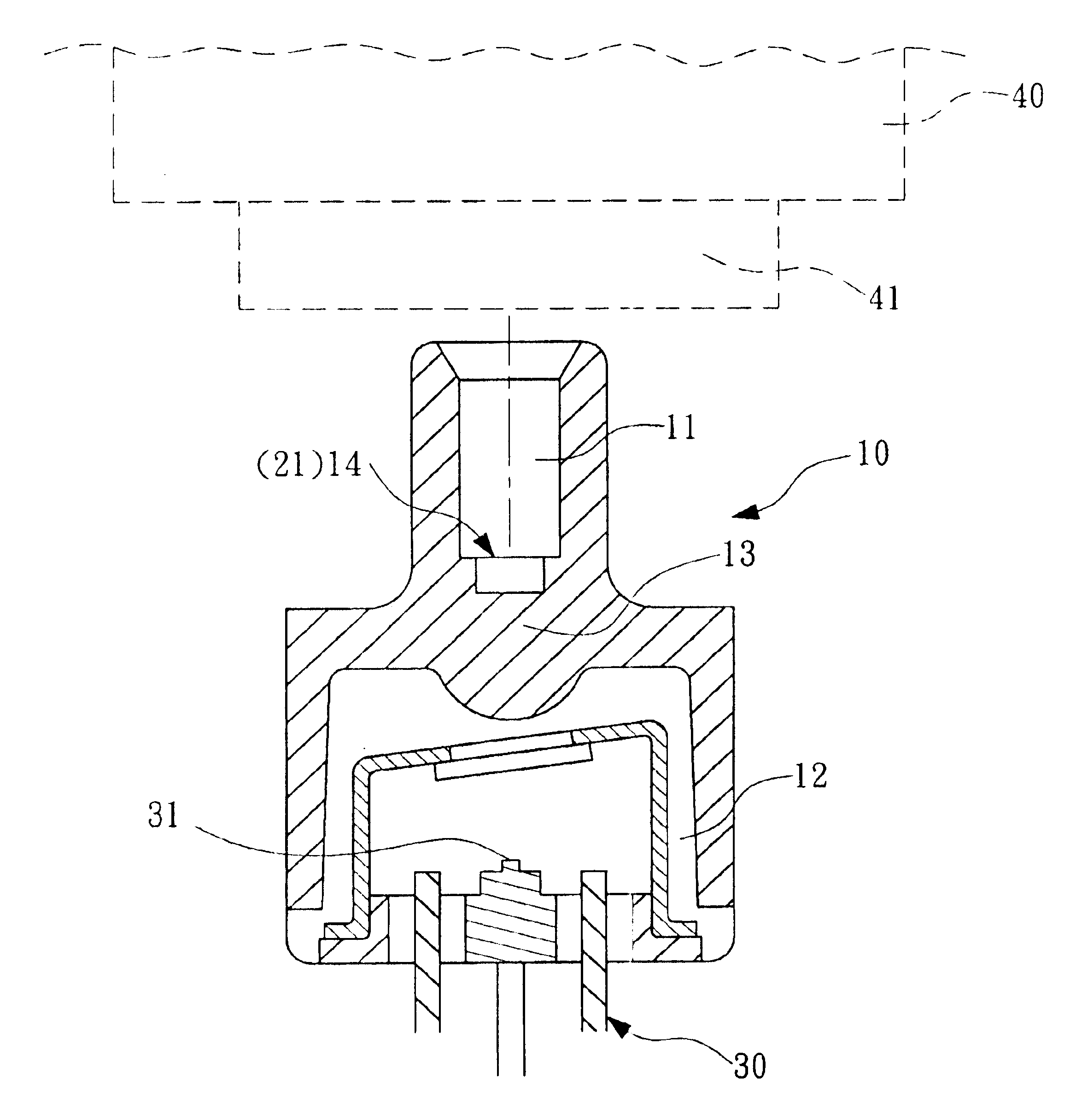
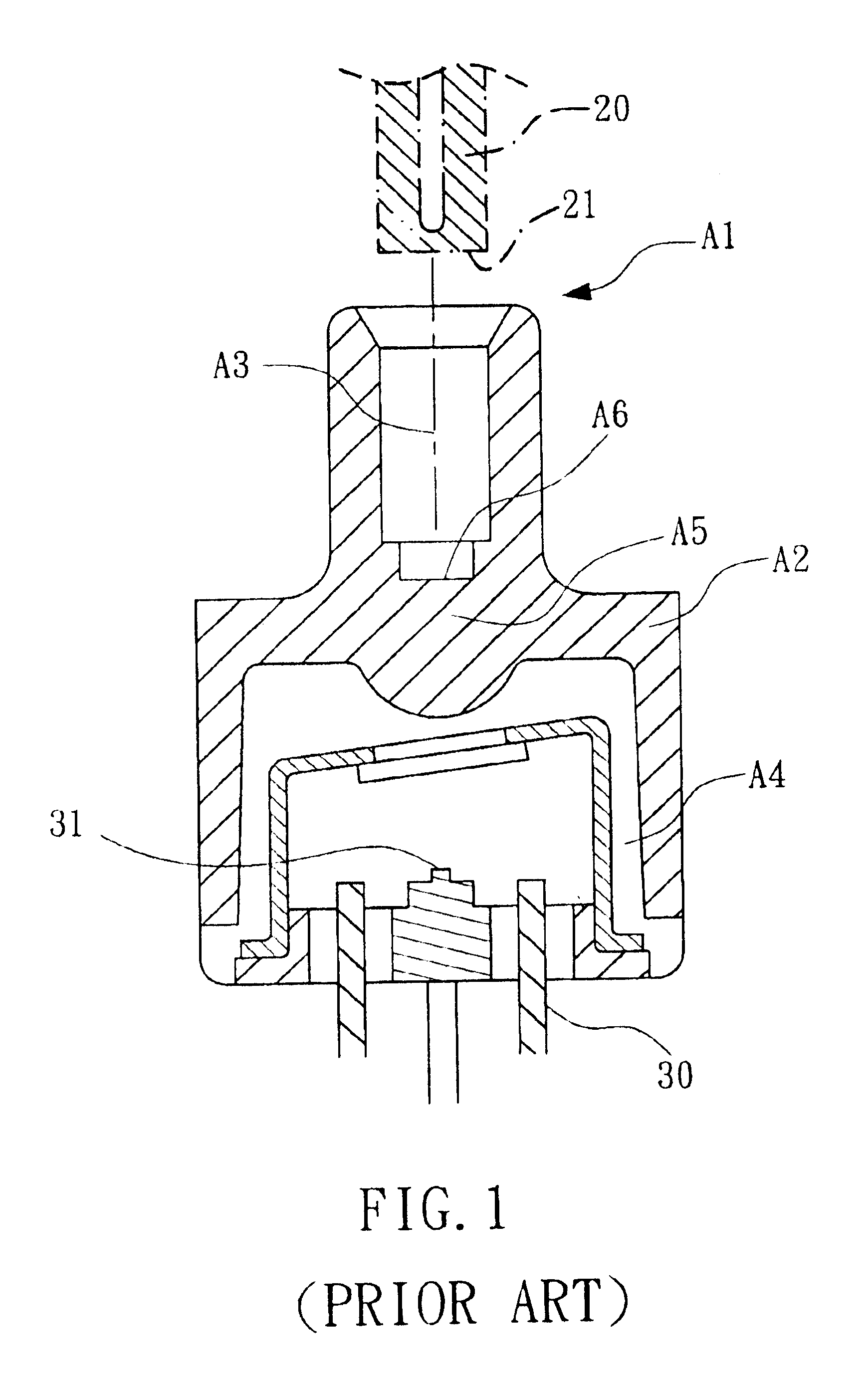
In a first aspect of the present invention, there is provided a method for measuring and assembling a TOSA having a one-piece housing, as shown in FIGS. 1, 4A, and 4B. The method includes the following steps:1. Prepare a housing 10 using a known plastic injection molding technique, as shown in FIG. 4A. The housing 10 is a one-piece structure similar to the conventional one-piece housings disclosed in, for example, U.S. Pat. No. 5,631,991; U.S. Pat. No. 6,432,733 B1; and U.S. Pat. No. 6,302,569 B1. The housing 10 is provided at a first end with a first aperture 11 for an optical fiber 20 to assemble thereto, and at a second end opposite to the first end with a second aperture 12 for a functional element 30 to assemble thereto. The functional element 30 may have differently designed assembling manners and functions, and may be, for example, a laser diode or a light emitting diode. In the case of a laser diode, the functional element 30 may be further divided into several different typ...


PUM


Abstract

In measuring and assembling a transceiver optical sub-assembly that includes a one-piece or two-piece housing having two opposite apertures separately for an optical fiber and a functional element to assemble thereto, and a lens located between the fiber and the functional element, an image sensor is aligned with the fiber aperture to set a focus on a fiber coupling plane in the housing, and a light spot presented on the fiber coupling plane by a laser beam emitted from the functional element through the lens, or an image of a light-emitting area or a receiving area of the functional element presented on the fiber coupling plane via the lens, is measured to adjust size and/or position thereof, so as to precisely align and fix the functional element to the housing.

Description

FIELD OF THE INVENTIONThe present invention relates to a method for measuring and assembling transceiver optical sub-assembly (OSA), in which an image sensor is aligned with a fiber aperture on a housing of the optical sub-assembly and set to focus on a fiber coupling plane in the housing, so as to detect a light spot presented on the fiber coupling plane by a laser beam emitted from a functional element through the lens, or an image of a light-emitting area or a receiving area of the functional element presented on the fiber coupling plane via the lens. By adjusting the size and position of the light spot or the image on the fiber coupling plane, the functional element is precisely aligned and then fixed in the housing. With the method, measuring procedures for the OSA are simplified and the transmission bandwidth for the optical fiber is optimized, enabling an increased rate of good yield of the finished OSA.BACKGROUND OF THE INVENTIONOptical sub-assemblies (OSA) used in optic-ele...

Claims


Application Information

Patent Timeline
CPCG02B6/4221G02B6/4204
Inventor DENG, JAU-JANCHU, I-LINCHEN, GUO-ZEN
Owner E PIN OPTICAL IND
Why Eureka
Try Eureka