

Alignment method and method for producing device using the alignment method
a technology of alignment method and alignment method, which is applied in the direction of photomechanical equipment, instruments, printing, etc., can solve the problems of reducing throughput, affecting the accuracy of alignment method, so as to achieve the effect of reducing throughput and improving alignment accuracy
- Summary
- Abstract
- Description
- Claims
- Application Information
AI Technical Summary
Benefits of technology
Problems solved by technology
Method used
Image

Examples
first embodiment
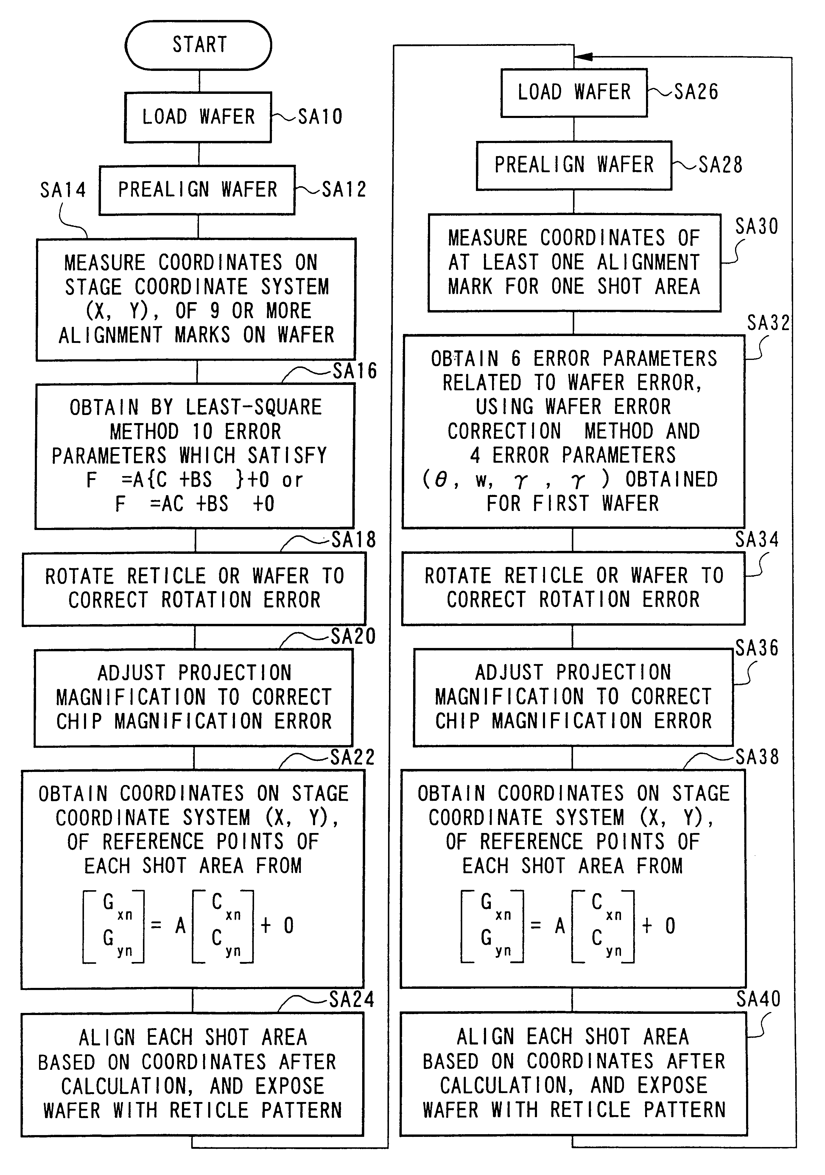
Hereunder is a detailed description of an alignment method according to a first embodiment of the present invention performed to solve the abovementioned problem.
FIG. 5 is a flowchart showing the processing sequence of the alignment method according to the first embodiment of the present invention.
First of all, in step SA10 in FIG. 5 the wafer 8 which is the exposure object, is loaded onto the wafer holder 9. Here, the description is made giving as an example the case where the first wafer of each lot, in other words the wafer of the first piece of each lot, is loaded.
In each shot area of the wafer 8, the chip patterns have already been respectively formed in the former step.
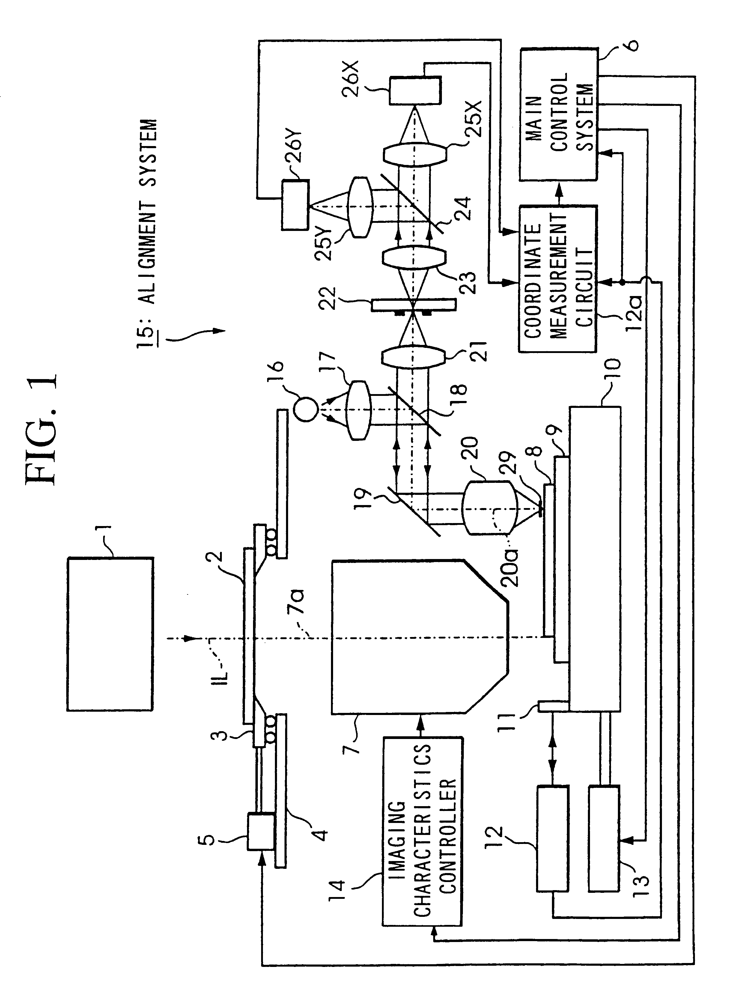
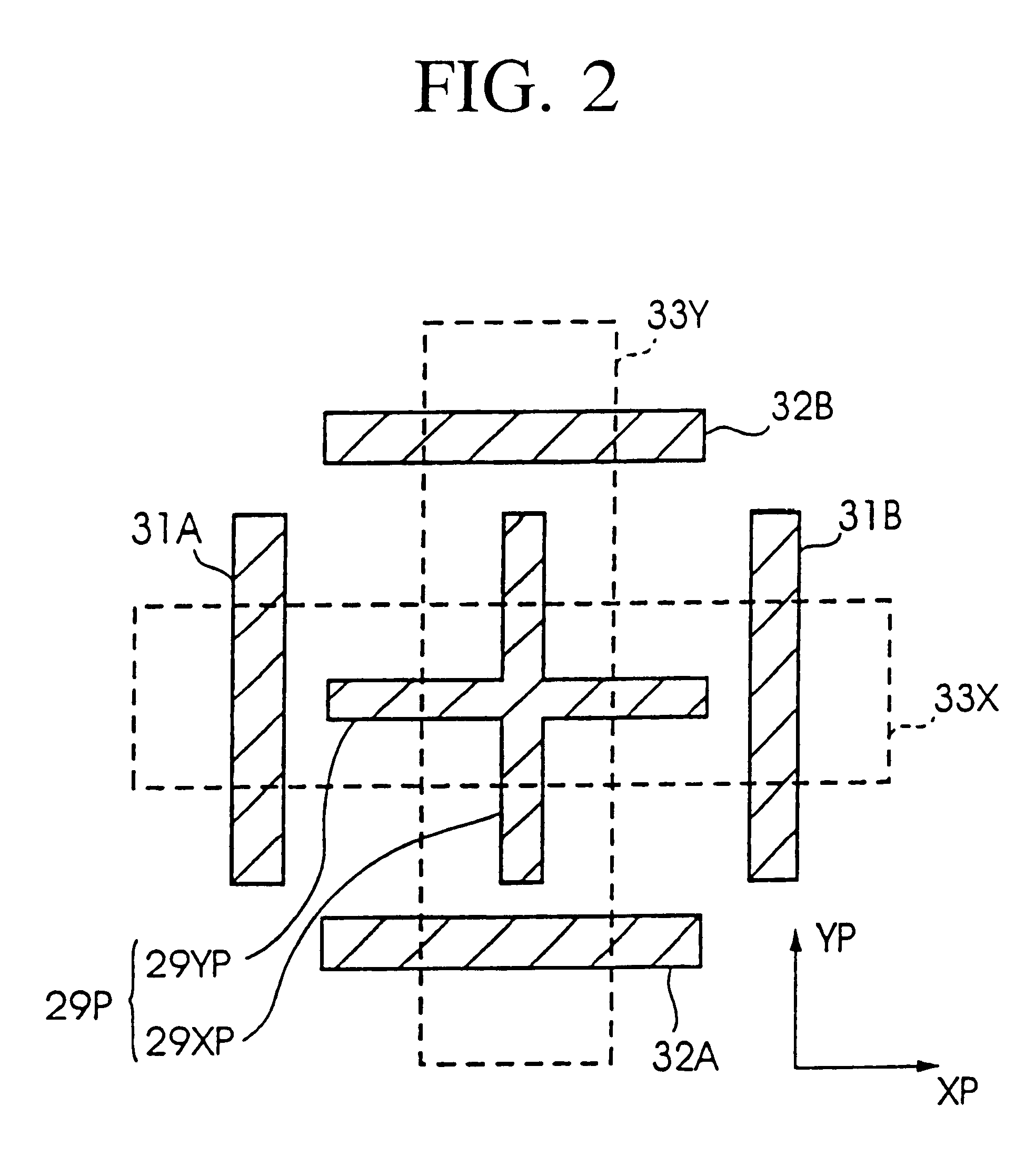
In addition, as shown in FIG. 3B, the four cross type alignment marks 29-n, 30-n, 34-n, and 35-n are respectively formed in each shot area 27-n on the wafer 8. Moreover, alignment of the reticle 2 is completed, and the amount of the displacement in the X, Y and the rotation direction of the reticle 2 with respec...
second embodiment
Next is a detailed description of an alignment method according to a second embodiment of the present invention.
FIG. 8 is a flowchart showing the processing sequence of the alignment method according to the second embodiment of the present invention.
First of all, in step SB10 in FIG. 8 the wafer 8 which is the exposure object, is loaded onto the wafer holder 9. Here, the description is made giving as an example the case where the first wafer of each lot, in other words the wafer of the first piece of each lot, is loaded.
In each shot area of the wafer 8, the chip patterns have already been respectively formed in the former step.
In addition, as shown in FIG. 3B, the four cross type alignment marks 29-n, 30-n, 34-n, and 35-n are respectively formed in each shot area 27-n on the wafer 8. Moreover, alignment of the reticle 2 is completed, and the amount of the displacement in the X, Y and the rotation direction of the reticle 2 with respect to the rectangular coordinate system prescribed...
third embodiment
Next is a description of a third embodiment of the present invention.
In the above described first and second embodiments, correction is performed using both the wafer error correction method and the shot error correction method, in performing alignment.
If the shot error correction method is used, accuracy of alignment is improved, however time is required for measuring alignment.
In this embodiment, a method of improving alignment accuracy using only the wafer error correction method without using the shot error correction method is described.
With the alignment method of this embodiment, position information (coordinate values) of a prescribed number of alignment marks within the plurality of alignment marks formed on each shot area is detected.
For example, in the case where the shot area is a square as shown in FIG. 3B, and the alignment marks are formed at the four corners of the shot area, then two alignment marks on one diagonal are measured.
When detecting a plurality of alignmen...
PUM
| Property | Measurement | Unit |
|---|---|---|
| width | aaaaa | aaaaa |
| width | aaaaa | aaaaa |
| areas | aaaaa | aaaaa |
Abstract
Description
Claims
Application Information