
Vibration damper assembly for the buckets of a turbine
a technology of vibration damper and bucket, which is applied in the field of turbines, can solve the problems of less effective damping, increased risk of inadequate damping, and lower potential for damper effectiveness
- Summary
- Abstract
- Description
- Claims
- Application Information
AI Technical Summary
Benefits of technology
Problems solved by technology
Method used
Image

Examples
Embodiment Construction
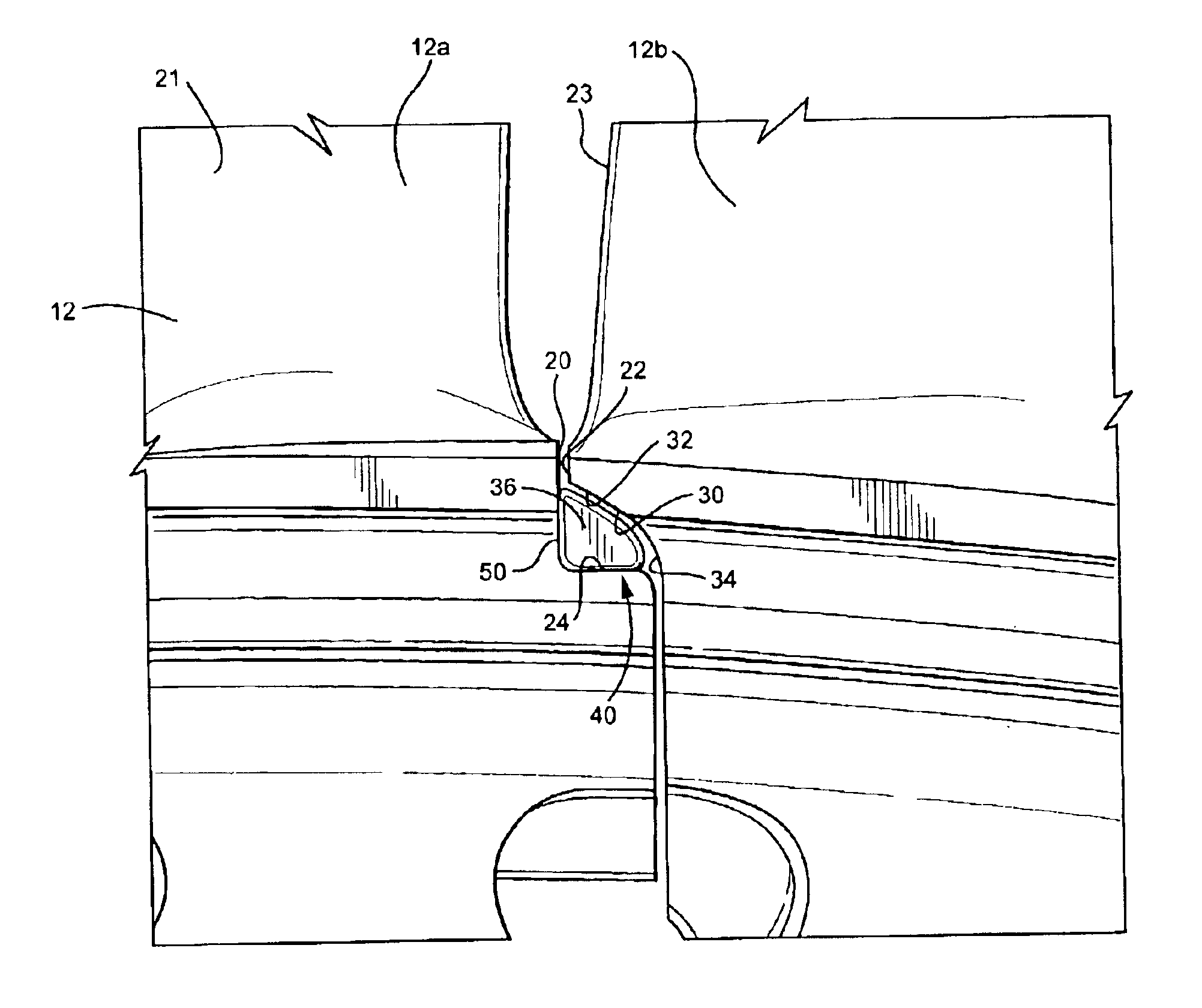
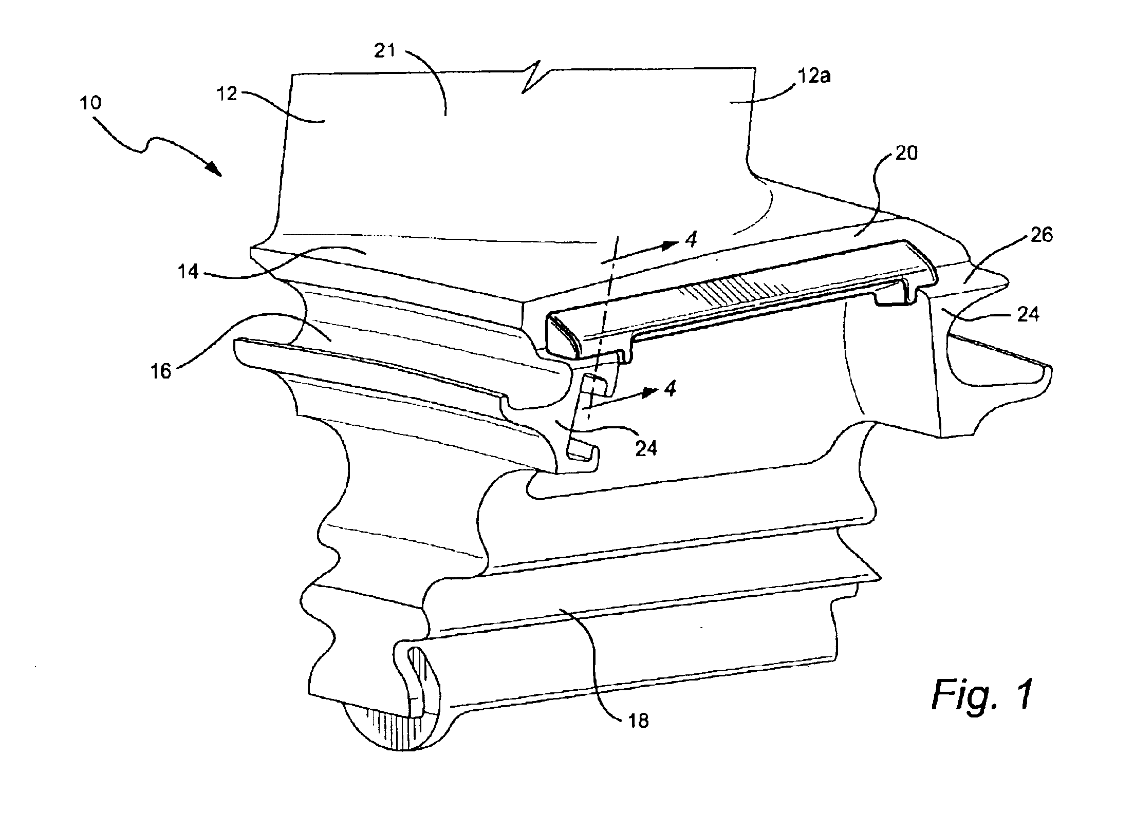
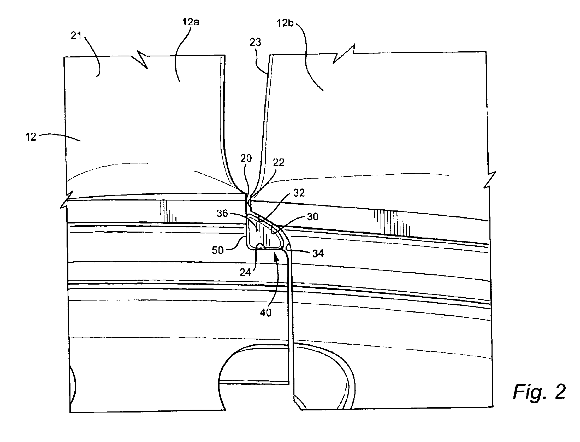
Referring now to the drawings, particularly to FIG. 1, there is illustrated a bucket, generally designated 10, including a bucket airfoil 12, a platform 14, a shank 16 and a dovetail 18. It will be appreciated that the bucket 10 as illustrated is one of a plurality of circumferentially spaced buckets secured to and about the rotor of a turbine. For example, gas turbines typically have a plurality of rotor wheels having axial or slightly off-axis dovetail-shaped openings for receiving the dovetail 18 of the bucket 10 whereby an annular array of circumferentially spaced buckets, including the airfoils 12, is provided about the rotor. From a review of FIGS. 1 and 2, the opposed and adjacent circumferential edges of each of the bucket platforms form slashfaces 20 and 22. As indicated previously, the airfoils 12 project into the gas stream and enable the kinetic energy of the fluid stream to be converted to mechanical energy through the rotation of the rotor.
As illustrated in FIG. 2, the...
PUM
 Abstract
Description
Claims
Application Information