
Tensioner lever for transmission device

a technology of transmission device and tensioner, which is applied in the direction of belt/chain/gearing, mechanical equipment, belt/chain/gearing, etc., can solve the problems of limited heat in the high temperature environment of the engine, deformation of the shoe, etc., and achieve the effect of reducing effort and reliably attaching the strength-maintaining pla

Inactive Publication Date: 2005-02-08
TSUBAKIMOTO CHAIN CO
View PDF21 Cites 12 Cited by
  • Summary
  • Abstract
  • Description
  • Claims
  • Application Information

AI Technical Summary

Benefits of technology

Accordingly, a general object of the invention is to provide a tensioner lever for a transmission device in which both a simplification of the tensioner lever and a weight reduction therein are attained, molding accuracy requirements and assembly effort are reduced, and easy disassembly can be carried out, making the lever more suitable for recycling.
Since the shape-retaining groove formed on the back surface of the shoe is fitted to a part of the strength-maintaining plate, deformation of the shoe due to heat in the high temperature environment encountered in an engine is limited. As a result, the shape of the surface of the shoe is stabilized and, at the same time, deviation of the shoe from its proper position and failure due to separation of the shoe from the plate resulting from continuous vibration of the chain or belt, are suppressed.
The locking pawl structure reliably attaches the strength-maintaining plate to the shoe by utilizing the elasticity of the locking pawls which are provided as part of the resin shoe. However, the locking pawl structure also provides for easy separation of the resin shoe from the strength-maintaining plate in disassembly, since the locking pawl can be bent by means of a tool such as a screwdriver to release the engagement of the locking pawl with the strength-maintaining plate.
In a preferred embodiment of the tensioner lever, separation and disassembly notches are provided on proximal portions of the locking pawls, allowing the pawls to be broken off in the process of disassembly of the lever, thereby reducing the effort required to separate the shoe from the strength-maintaining plate in the disassembly operation.
A projection for limiting lateral deviation of the shoe relative to the plunger of a tensioner is preferably provided on the plunger engaging portion of the shoe. The deviation-limiting projection allows the lever to move reliably with forward and backward movement of the plunger of the tensioner, without lateral deviation.

Problems solved by technology

Since the shape-retaining groove formed on the back surface of the shoe is fitted to a part of the strength-maintaining plate, deformation of the shoe due to heat in the high temperature environment encountered in an engine is limited.

Method used


Image

  • Tensioner lever for transmission device
  • Tensioner lever for transmission device
  • Tensioner lever for transmission device

Examples


Embodiment Construction

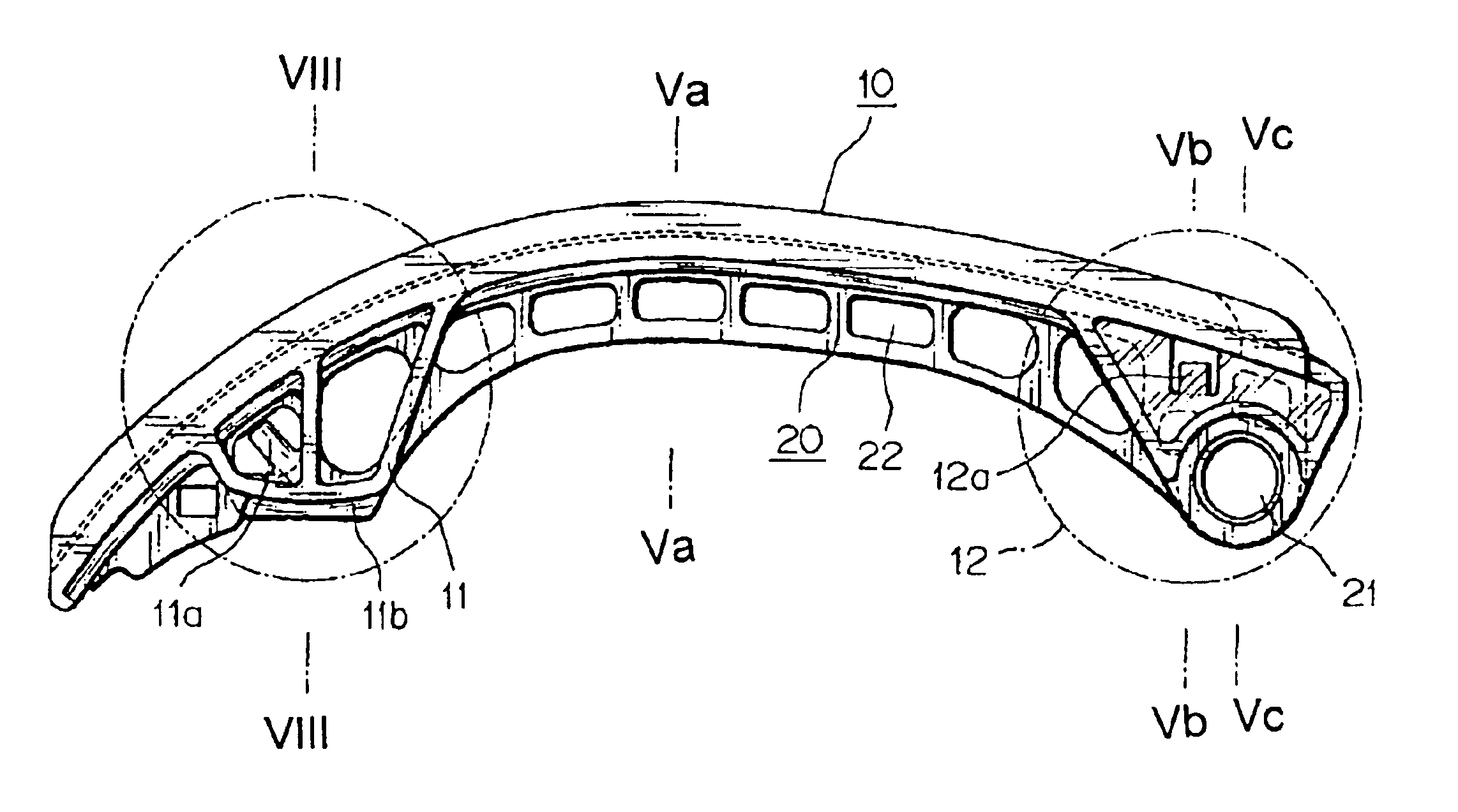
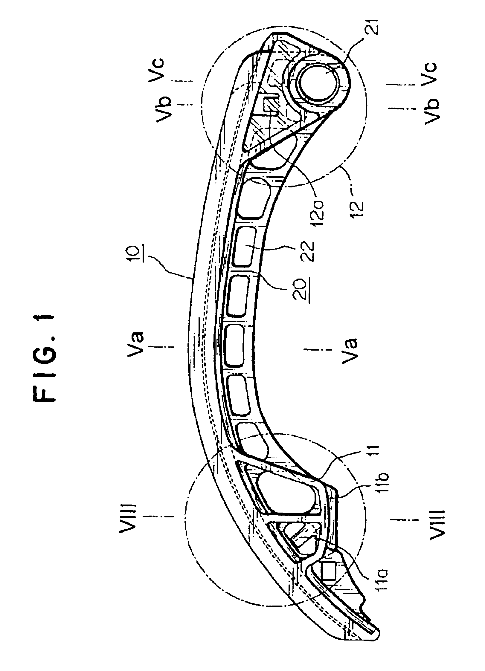
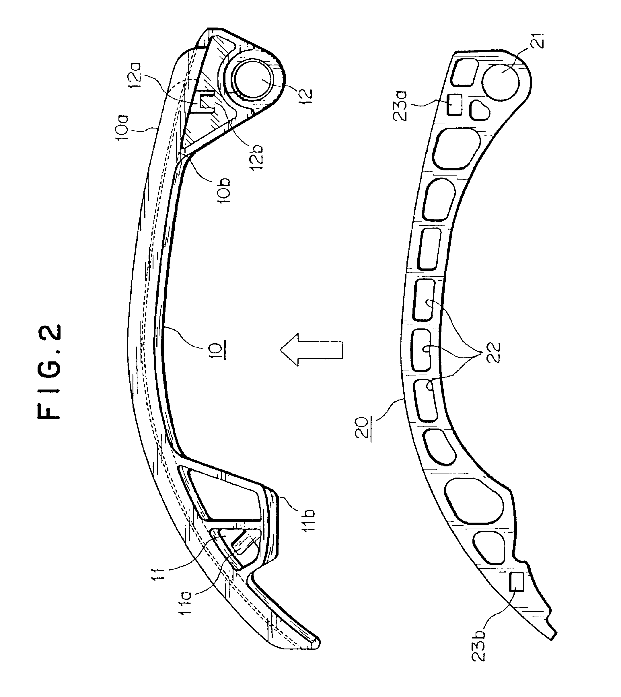
The tensioner lever shown in FIG. 1 is a two-piece structure comprising a resin shoe 10 shaped to receive chain which slides along the shoe in a longitudinal direction, and a strength-maintaining plate 20, mountable on a wall of an engine enclosure, for supporting the shoe.

As shown in FIG. 2, the shoe 10 has a front surface 10a on which the chain slides in a longitudinal direction, and a back surface 10b having a plunger engaging portion 11 which can be contacted freely by the plunger T1 (FIG. 8) of a tensioner under pressure, and a shaft bearing portion 12 through which a mounting shaft (not shown) extends, the mounting shaft being typically fixed to a wall of an engine enclosure. The plunger receiving portion 11 and the shaft bearing portion 12 are respectively formed near a distal end of the shoe and a proximal end thereof. A concave, shape-retaining groove 13 is formed along the longitudinal direction of the lever, as shown in FIGS. 5(a), 5(b), 6, 7, and 8. The groove extends th...


PUM


Abstract

A tensioner lever for a chain or belt power transmission comprises a resin shoe having a shoe surface on which the chain or belt slides, and a back surface with a plunger-engaging part adjacent one end and a lever shaft bearing adjacent the other end. A shape-retaining groove extends longitudinally along the shoe through the plunger engaging part and the lever shaft bearing. A part of a strength-maintaining plate is fits in the shape-retaining groove and a part of the strength-maintaining plate is exposed.Simplification and weight reduction in the tensioner lever can be realized, and molding accuracy requirements are reduced. Assembly is simplified by pawls formed in openings in a side wall of the shoe, which cooperate with locking holes in the strength-maintaining plate. The pawls simplify disassembly for recycling and may be notched so that they can be broken away. A projection is provided on the plunger-engaging part of the shoe for limiting lateral deviation of the lever relative to the tensioner plunger.

Description

BACKGROUND OF THE INVENTIONThis invention relates to a tensioner lever used for guiding and tensioning a chain or belt in a transmission device. The transmission device may be a device that transmits power from a driving sprocket to a driven sprocket through an endless chain or toothed belt engaged with both sprockets, or a device that transmits power from a driving pulley to a driven pulley by an endless belt engaged with both pulleys.Various machines, for example internal combustion engines, include a transmission device that transmits power through an endless chain, a belt or the like that travels in a closed loop. In such a transmission device, a tensioner lever, as shown in FIG. 9, FIG. 10, or FIG. 11, is used to apply appropriate tension to the belt or chain while in sliding contact with the belt or chain. The tensioner lever also functions to prevent vibration of the chain or belt, including vibration in the plane of the loop and lateral vibration.Tensioner lever A, shown in ...

Claims


Application Information

Patent Timeline
Patent Type & Authority Patents(United States)
IPC IPC(8): F16H7/18F16H7/00F16H7/08F16H7/06
CPCF16H7/18F16H2007/0872
Inventor KONNO, MASAHIKO
Owner TSUBAKIMOTO CHAIN CO
Learn More