Method and apparatus for cleaning of a milking plant

Inactive Publication Date: 2005-02-08
DELAVAL HLDG AB
View PDF14 Cites 11 Cited by
  • Summary
  • Abstract
  • Description
  • Claims
  • Application Information

AI Technical Summary

Benefits of technology

A The present invention is directed towards the milking plant for milking animals, such as cows, wherein milk collecting means, preferably in the form of teat cups, are attached to the teat of the animal whereafter milk is taken from the animal by use of vacuum. The milk is transported by a milk line system to a milk storage means comprising a cooling tank in which milk from all, or at least several animals, is stored. For cleaning purposes the milk line system from each milking station, that is milk collecting means, can be shut of from the milk tank by valve means in order for separate cleaning of the milk line system. The invention is characterised by preventing any possible leakage of detergent from a cleaning fluid to the milk that has been collected in the milk tank, by providing a pressure difference between the two fluids.
The two fluid

Problems solved by technology

The two fluids are mechanically separated by the said valve means, but there is a always a risk for a valve to leak.
Milk however can of course leak out through the valve into the cleaning fluid.
Although neither this is desirable, the damage is limited to a somewhat decreased

Method used


Image

  • Method and apparatus for cleaning of a milking plant
  • Method and apparatus for cleaning of a milking plant
  • Method and apparatus for cleaning of a milking plant

Examples


Embodiment Construction

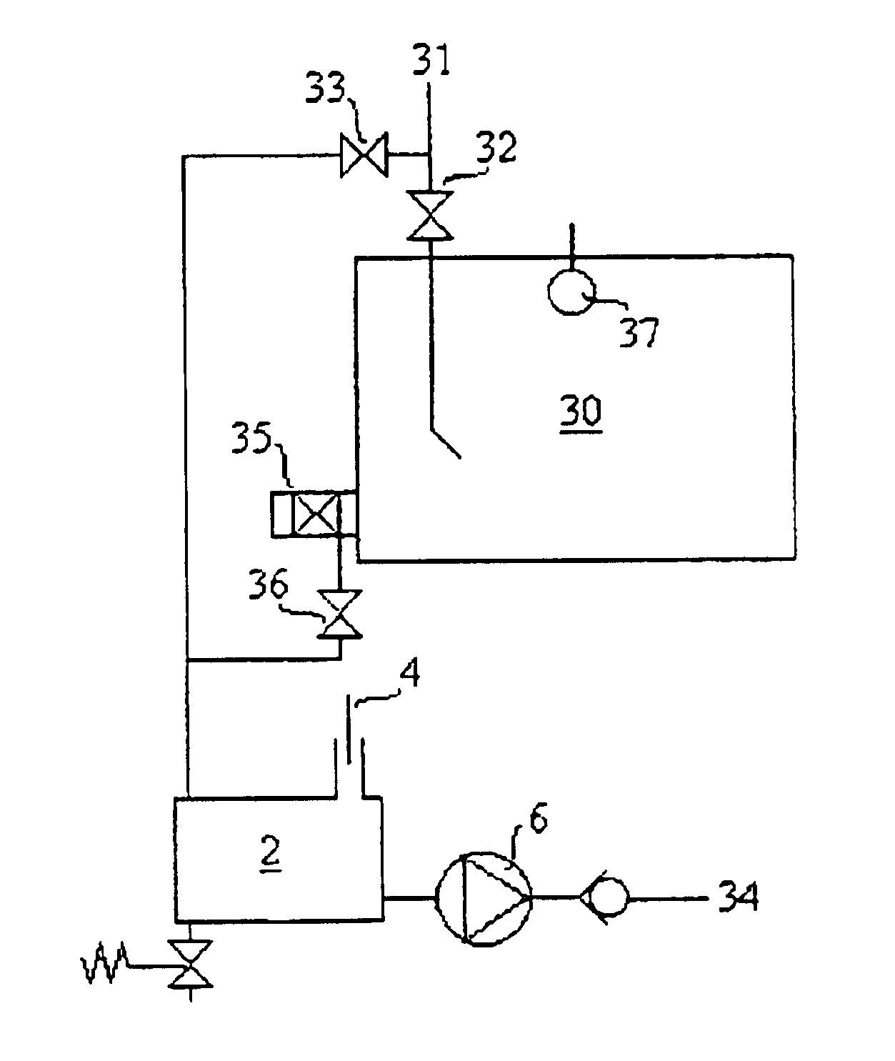
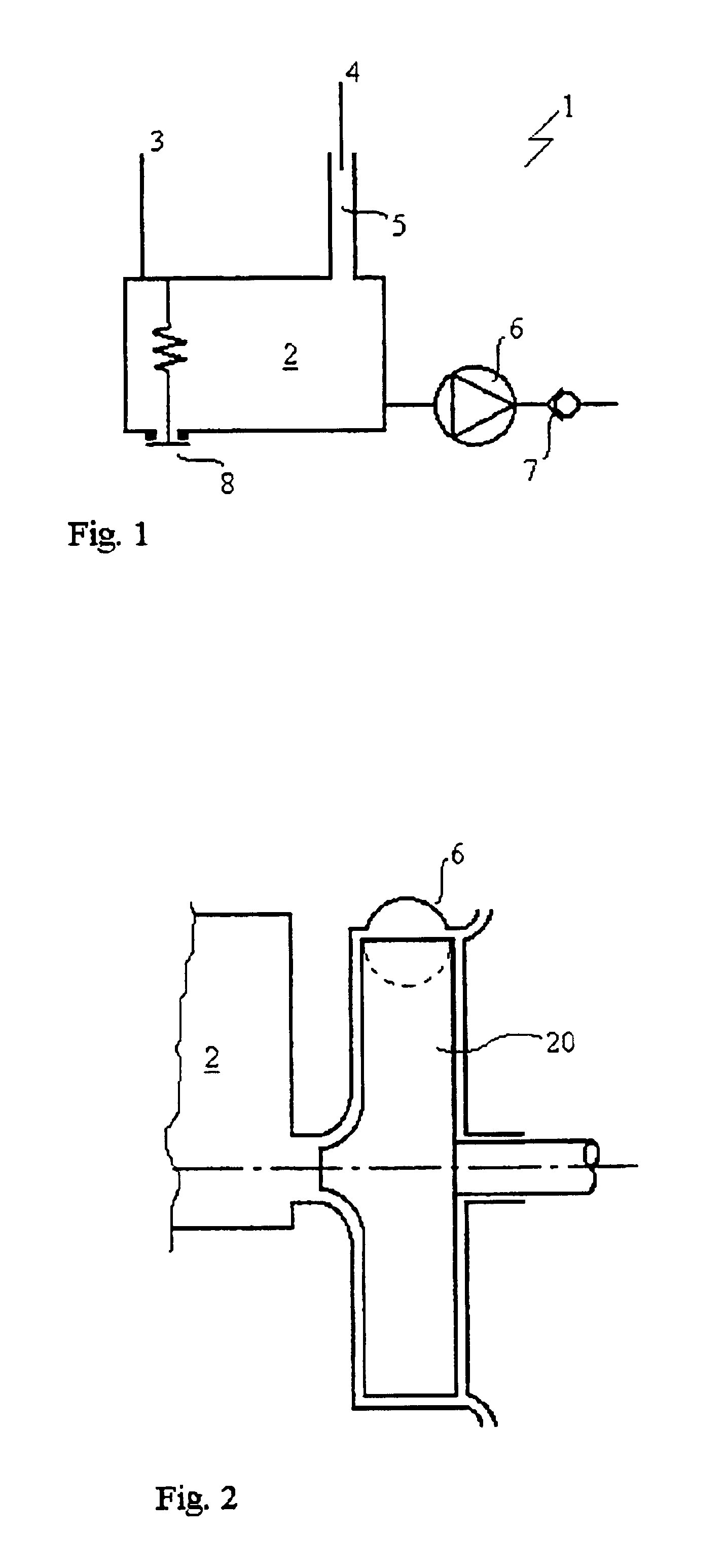
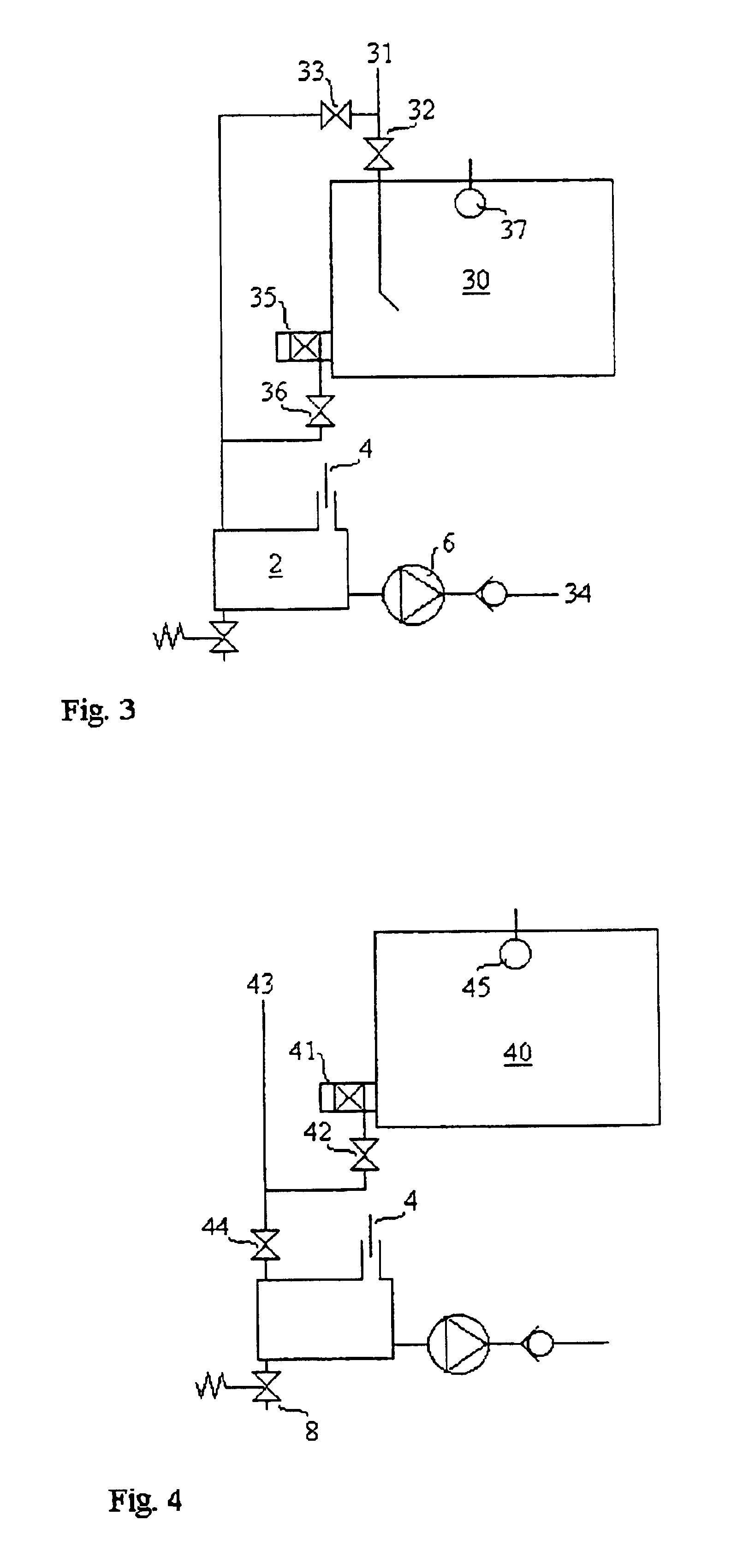
During cleaning of milking equipment it is common to suck in and rinse water, alkali washing solution, sour washing solution and disinfection solution through the teat cups from a container at atmospheric pressure. The underpressure in the connection point, i.e. the washing shelf with the teat dummies, makes the connection easy: the teat cups hold on by suction and no cleaning fluid leaks out. This method has turned out to be reliable and is useful also for milking robots. The cleaning fluid container is generally comprised as a part of a washing machine. The cleaning fluid is sucked and pumped through the milking equipment to a connection point were it is to be returned to the cleaning fluid container, thereby obtaining a circulation loop. In the vicinity of this connection point in a milking equipment, a system separating valve which must not leak is located. The system separating valve, which must be present, is placed between the milk transport line system (milk line system) and...


PUM


Abstract

A milking plant for milking animals, such as cows, wherein milk collecting means, prefeably in the form of teat cups, are attached to the teat of the animal whereafter milk is taken from the animal by use of vacuum. The milk is transported by a milk line system (31) to milks storage means comprising a cooling tank (30). For cleaning purposes the milk line system from each milk collecting means can be shut off from the milk tank by valve means (32) in order for separate cleaning of the milk line system. The invention is characterized by preventing any possible leakage of detergent from a cleaning fluid to the milk that has been collected in the milk tank, by providing a pressure difference between the two fluids. The pressure difference between the fluids is preferably achieved by connecting the cleaning fluid to the vacuum supply (4) of the milking plant.

Description

TECHNICAL FIELDThe present invention relates to a milking plant for milking animals, such as cows, and preferably though not exclusively to plants comprising milking robots operating with vacuum to collect milk from the animals, wherein the milk is transported by a milk line system to a cooling tank. The invention relates particularly to the cleaning of milking equipment using a cleaning fluid such as water, or a detergent, flowing through the milk line system.BACKGROUND OF THE INVENTIONIn traditional milking with manual handling of the equipment a large number of cows are milked simultaneously one to four hours every morning and night. After each milking a manual adjustment is made wherein teat cups used to collect milk from the cows are placed on teat dummies. Rinsing water and later a detergent solution, is sucked from a washing machine through the teat dummies into the teat cups, and onwards through the milking equipment. The fluid transport is driven by a vacuum suction, for in...

Claims


Application Information

Patent Timeline
IPC IPC(8): A01J5/04A01J7/02A01J7/00A01J5/00B08B3/04B08B9/053B08B5/04B08B5/00B08B9/02A01J
CPCA01J7/022
Inventor LIDMAN, MAGNUS
Owner DELAVAL HLDG AB
Why Eureka
Try Eureka