

Electrophotographic photoreceptor, and electrophotographic apparatus using the same
- Summary
- Abstract
- Description
- Claims
- Application Information
AI Technical Summary
Benefits of technology
Problems solved by technology
Method used
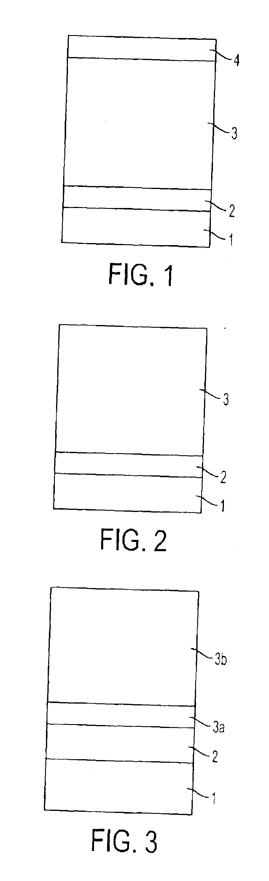
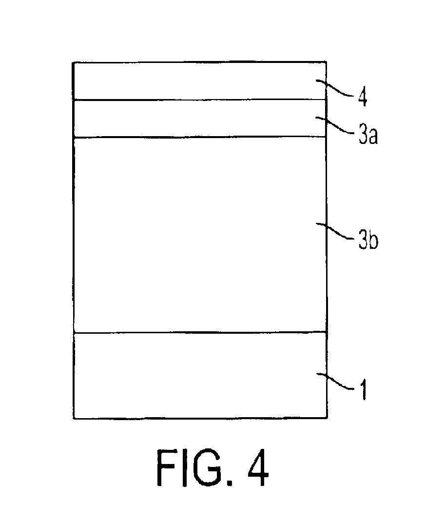
Image

Examples
synthesis example 1
Synthesis of Compound of Above-mentioned Specific Example I-21
(Reaction formula 1-1)(Starting materials and reagents)4-bromo-2,6-di-t-butyl-1-benzene (A-1) 50 mmol (17.9 g)THF (tetrahydrofuran)100 mln-butyl lithium (1.6M hexane solution) 60 mmol (38 ml)2,5-dibenzoylthiophene (B-1) 20 mmol (5.8 g)THF (tetrahydrofuran) 20 mlAmmonium chloride aqueous solution 10 mlTetrabutylammonium fluoride (TBAF) 50 mmol (26.1 g)(1.0M THF solution)p-toluenesulfonic acid monohydrate (p-TsOH)Small amountToluene100 ml
Method(1) The compound A-1 was weighed out into a 3-mouth flask, and THF (100 ml) was added.(2) The n-butyl lithium was instilled in over 30 minutes under an N2 atmosphere at −78° C. (dry ice-ethanol bath), and stirring was carried out for 30 minutes. A THF solution (20 ml) of the compound B-1 was then instilled in over 30 minutes under the same conditions, and stirring was carried out for 3 hours.(3) Approximately 10 ml of saturated ammonium chloride aqueous solution was added, thus carryi...
synthesis example 2
Synthesis of Compound of Above-mentioned Specific Example I-51
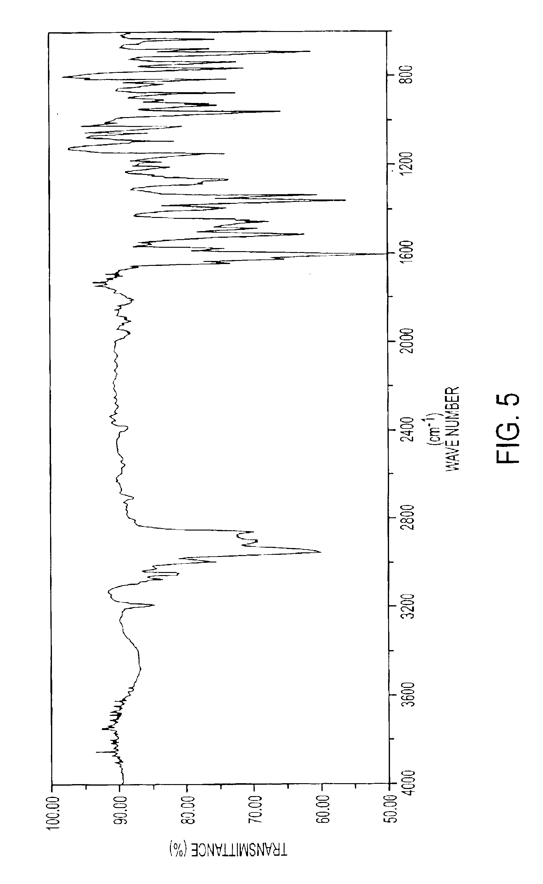
The same method was carried out as in Synthesis Example 1, except that the 20 mmol (5.8 g) of 2,5-dibenzoylthiophene (B-1) used in Synthesis Example 1 was replaced with 20 mmol (6.1 g) of 2,5-dithenoylthiophene (B-2), whereby the compound represented by above-mentioned formula I-51 was obtained. The yield was 4.9 g (36.0%), and the MS was m / z 681 (M+). The IR spectrum of the compound of formula I-51 is shown in FIG. 7, and the 1H-NMR spectrum is shown in FIGS. 8A-8B.
PUM
| Property | Measurement | Unit |
|---|---|---|
| Fraction | aaaaa | aaaaa |
| Fraction | aaaaa | aaaaa |
| Fraction | aaaaa | aaaaa |
Abstract
Description
Claims
Application Information