Cold-cathode discharge lamp and lamp device having reduced sputtering on internal lead-in wire

a technology lamp device, which is applied in the direction of low-pressure discharge lamps, gas-filled discharge tubes, discharge tubes luminescnet screens, etc., can solve the problems of interfering with the longer and achieve the effect of reducing sputtering and prolonging the life of cold cathode discharge lamps

Inactive Publication Date: 2005-02-08
PANASONIC CORP
View PDF9 Cites 11 Cited by
  • Summary
  • Abstract
  • Description
  • Claims
  • Application Information

AI Technical Summary

Benefits of technology

According to the present invention, it is possible to suppress sputtering o...

Problems solved by technology

Thus, more sputtering materials are generated by increased sputtering on the lead-in wire, and mercu...

Method used


Image

  • Cold-cathode discharge lamp and lamp device having reduced sputtering on internal lead-in wire
  • Cold-cathode discharge lamp and lamp device having reduced sputtering on internal lead-in wire
  • Cold-cathode discharge lamp and lamp device having reduced sputtering on internal lead-in wire

Examples


embodiment 1

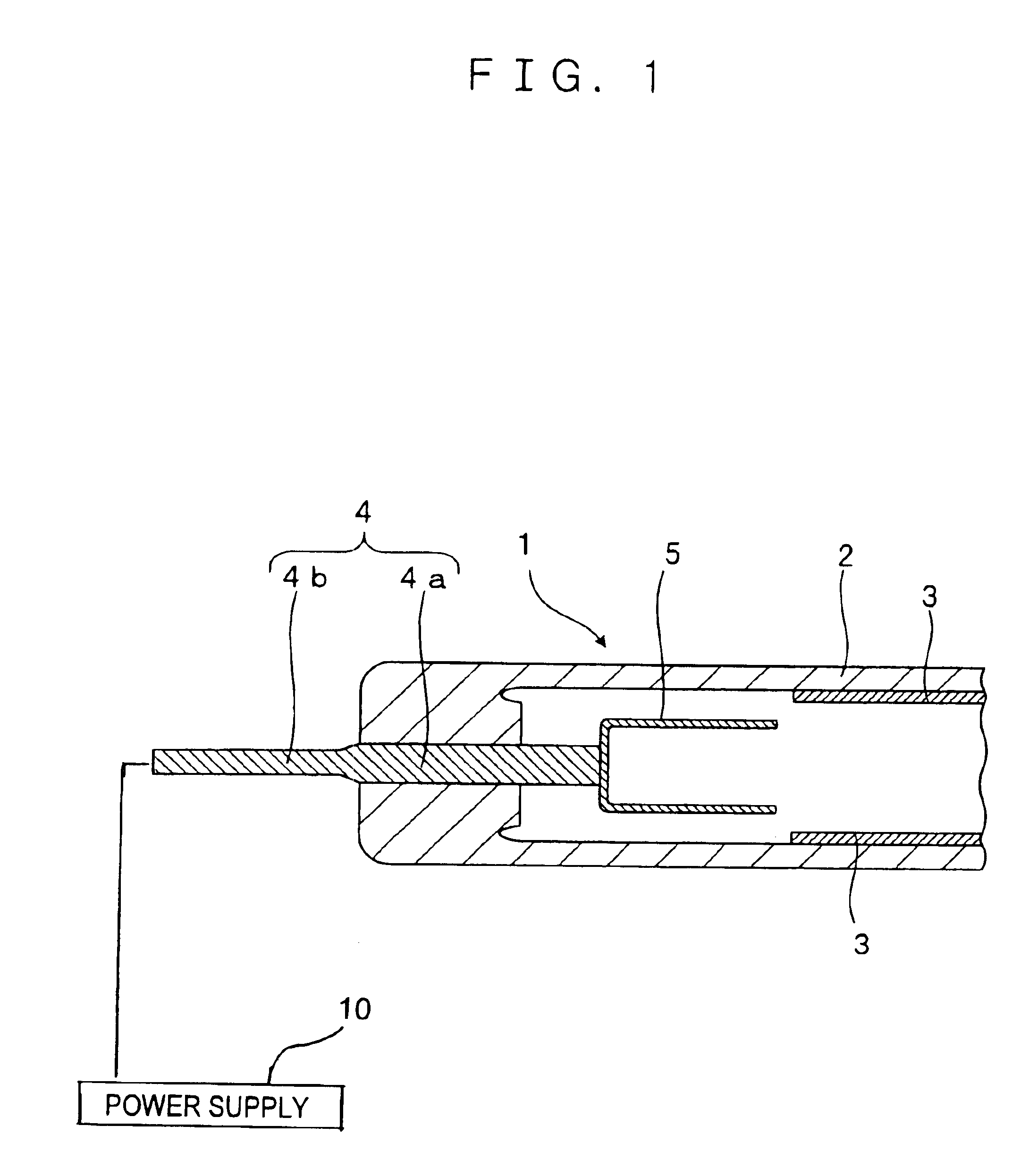
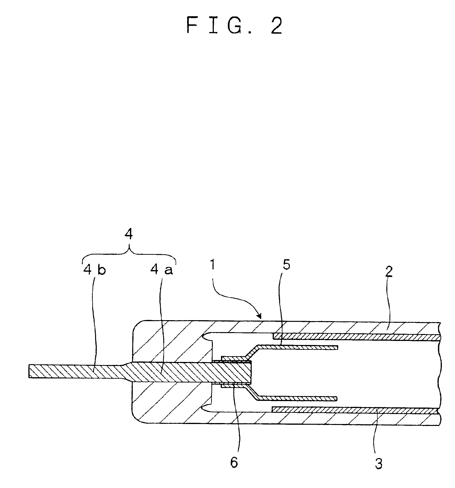
FIGS. 1 and 2 show (Embodiment 1) of the present invention.

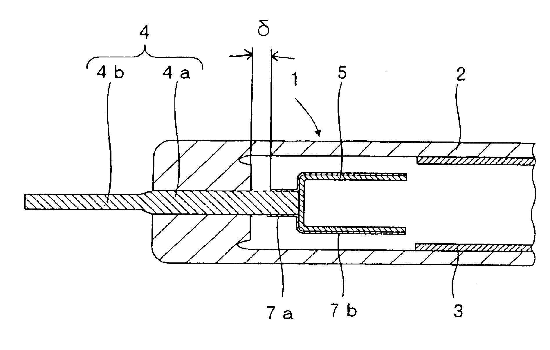
As shown in FIG. 1, a lead-in wire 4 is provided at an end of a lighting tube 1 having a phosphor 3 applied onto the inner surface of a glass tube 2. The lead-in wire 4 has one end connected to an external power supply 10 and the other end connected to a conductive cylindrical electrode 5. A suitable amount of mercury and rare gas is contained into the lighting tube 1, and sealing is performed on the lighting tube 1.

The lead-in wire 4 is constituted by an internal lead-in wire 4a, which is connected in the lighting tube 1 to the non-discharge end of the cylindrical electrode 5 and hermetically seals the lighting tube 1, and an outer lead-in wire 4b connected to the external power supply via the internal lead-in wire 4a outside the lighting tube 1.

When current is supplied to the cylindrical electrode 5 from the external power supply via the lead-in wire 4, discharge occurs in the lighting tube 1, and ultraviolet radiation gen...

embodiment 2

FIG. 3 shows (Embodiment 2) of the present invention.

(Embodiment 2) is different from (Embodiment 1) in that at least a part of the surface of an internal lead-in wire 4a is made of a material having a larger work function value than that of a material that forms the inner surface of a cylindrical electrode 5.

Hereinafter, explanation will be made according to specific examples.

As shown in FIG. 3, in a cold-cathode discharge lamp configured as FIG. 1, a glass tube 2 is made of a hard glass material such as borosilicate glass, and the internal lead-in wire 4a is made of a material such as tungsten, which is approximate in expansion coefficient to the hard glass material that forms the glass tube 2.

A material of the cylindrical electrode 5 is not particularly limited. For example, the cylindrical electrode 5 is made of tungsten, which is the same material as the internal lead-wire 4a, nickel having a larger work function value than that of the material that forms the internal lead-in w...

embodiment 3

FIG. 4 shows (Embodiment 3) of the present invention.

As to a cold-cathode discharge lamp configured as FIG. 3, (Embodiment 3) is different from (Embodiment 2) in that at least a part of the surface of an internal lead-in wire 4a is covered with insulating coatings 8a and 8b, instead of covering the outer surface of the internal lead-in wire 4a and the outer surface of the cylindrical electrode 5 with a material having a large work function value. Reference character “δ” identifies a portion of such example arrangement internal wire 4a not covered by film 8a,8b in FIG. 4.

To be specific, an oxide film 9 is formed on a part of the internal lead-in wire 4a that abuts a glass tube 2 on the internal lead-in wire 4a. The internal lead-in wire 4a is made of stainless (e.g., stainless containing 6% of chromium referred to as a 426 alloy, 42 to 47% of nickel, and iron accounting for the remainder). On the outer circumferential surface of the internal lead-in wire 4a in the lighting tube 1, an...


PUM


Abstract

The present invention has an object to provide a cold-cathode discharge lamp which can suppress sputtering on a lead-in wire and reduce consumption of mercury so as to achieve a longer lifetime without increasing an amount of applied mercury. The cold-cathode discharge lamp of the present invention is characterized in that a lead-in wire connected to a cylindrical electrode in a lighting tube is made of a material same as a material that forms the cylindrical electrode. It is possible to suppress concentration negative glow discharge shifted to the lead-in wire and to allow the electrode to be covered with even negative glow discharge. Thus, it is possible to reduce mercury consumed by excessive sputtering on the outer surface of the internal lead-in wire and to achieve a longer lifetime of the cold-cathode discharge lamp.

Description

FIELD OF THE INVENTIONThe present invention relates to a cold-cathode discharge lamp used for backlighting of a liquid crystal display and the like.BACKGROUND OF THE INVENTIONA cold-cathode discharge lamp used as a light source for backlighting of a liquid crystal display is configured such that cylindrical or plate metal is provided as an electrode in a lighting tube, which has a phosphor applied onto the inner surface of a glass tube, mercury and the like is contained therein, and the phosphor is excited by ultraviolet radiation that is generated in the lighting tube by discharge to provide visible radiation.As to such a cold-cathode discharge lamp, a variety of studies on miniaturization, a smaller diameter, higher luminance, and a longer lifetime have been conducted in response to diversity of liquid crystal displays. For example, Japanese Patent Laid-Open No. 4-137429 proposes a cold-cathode discharge lamp, in which in order to reduce mercury consumed by sputtering in a lamp, a...

Claims


Application Information

Patent Timeline
IPC IPC(8): H01J61/38H01J61/067H01J61/36H01J61/78
CPCH01J61/38H01J61/78
Inventor YAMASHITA, HIROFUMIYAMAZAKI, HARUOTERADA, TOSHIHIROKIHARA, SHINJI
Owner PANASONIC CORP
Why Eureka
Try Eureka