Integrated optical system for endoscopes and the like

a technology of endoscopes and integrated optical systems, applied in the field of optical lens systems, can solve the problems of high insensitivity to tilt and decentration of their components, and achieve the effects of reducing the number of elements, facilitating mass production, and long curvature radii

Inactive Publication Date: 2005-02-08
RES CORP TECH INC
View PDF36 Cites 17 Cited by
  • Summary
  • Abstract
  • Description
  • Claims
  • Application Information

AI Technical Summary

Benefits of technology

Several exemplary embodiments of the present invention are disclosed which provide an integrated optical system suitable for endoscopes, borescopes, dental scopes, and the like. One aspect of the present invention is an endoscope having a reduced number of elements compared with conventional endoscopes. The elements may advantageously have relatively long radii of curvature which facilitates their mass production. Furthermore, the elements are not necessarily of a meniscus shape.

Problems solved by technology

Further, many of the embodiments disclosed herein are highly insensitive to tilt and decentration of their components.

Method used


Image

  • Integrated optical system for endoscopes and the like
  • Integrated optical system for endoscopes and the like
  • Integrated optical system for endoscopes and the like

Examples


##diments 1-11

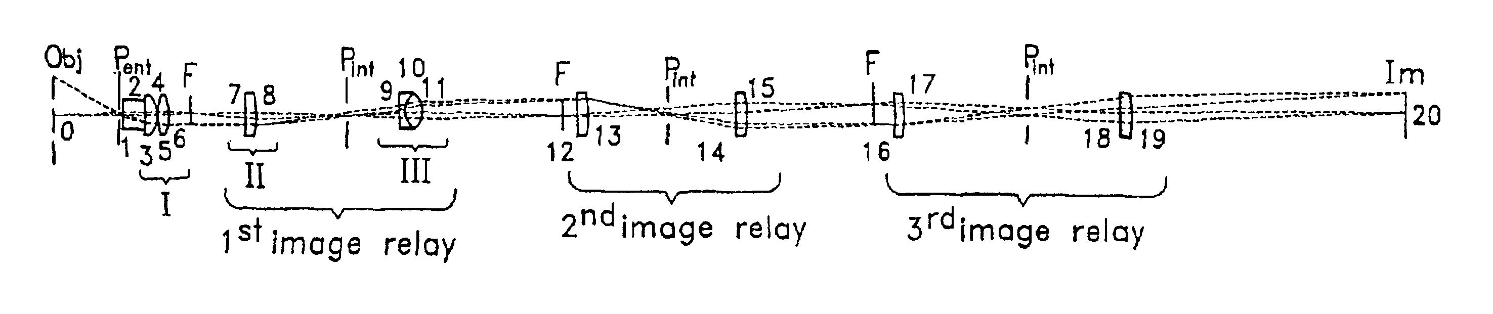
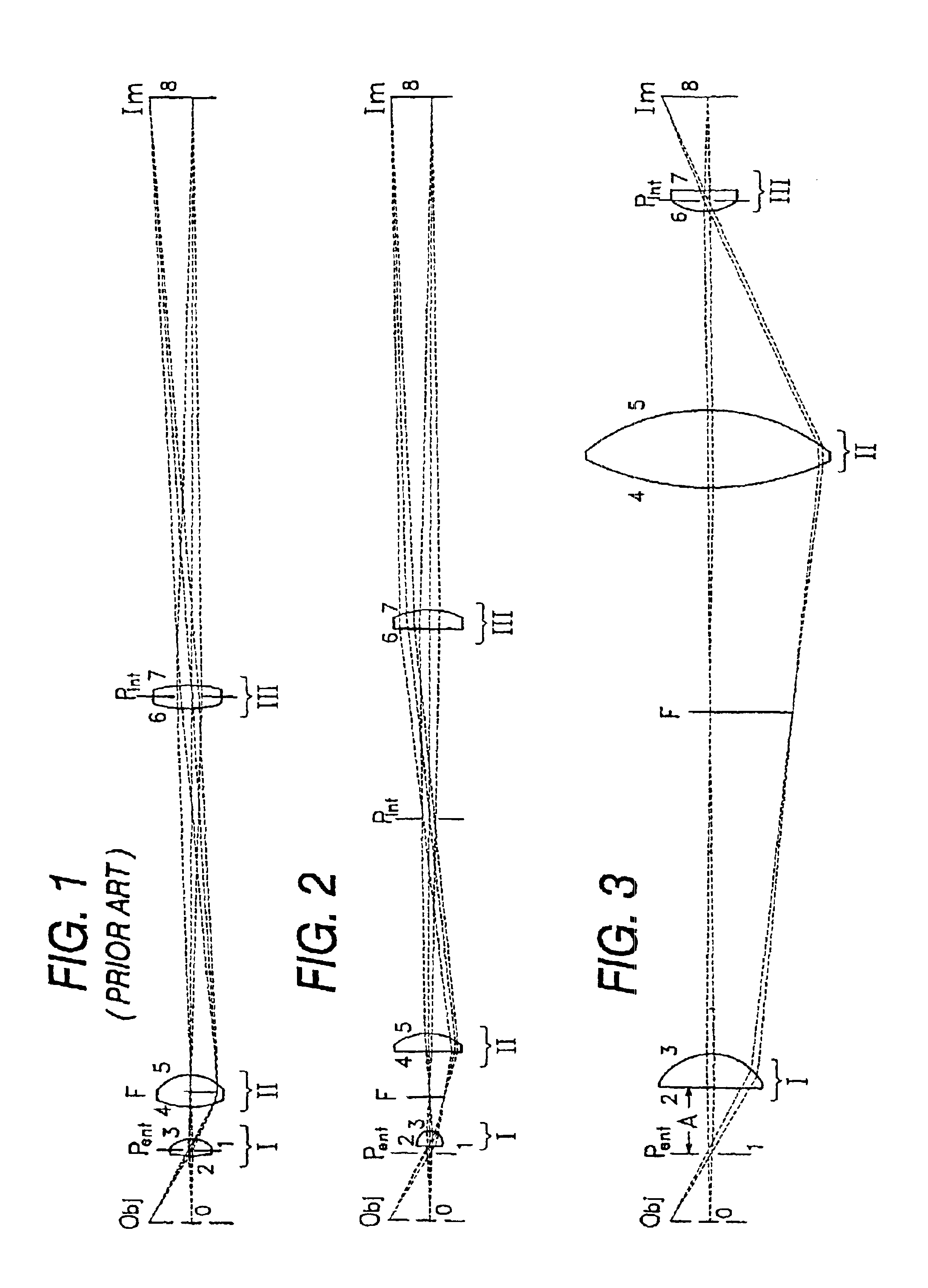
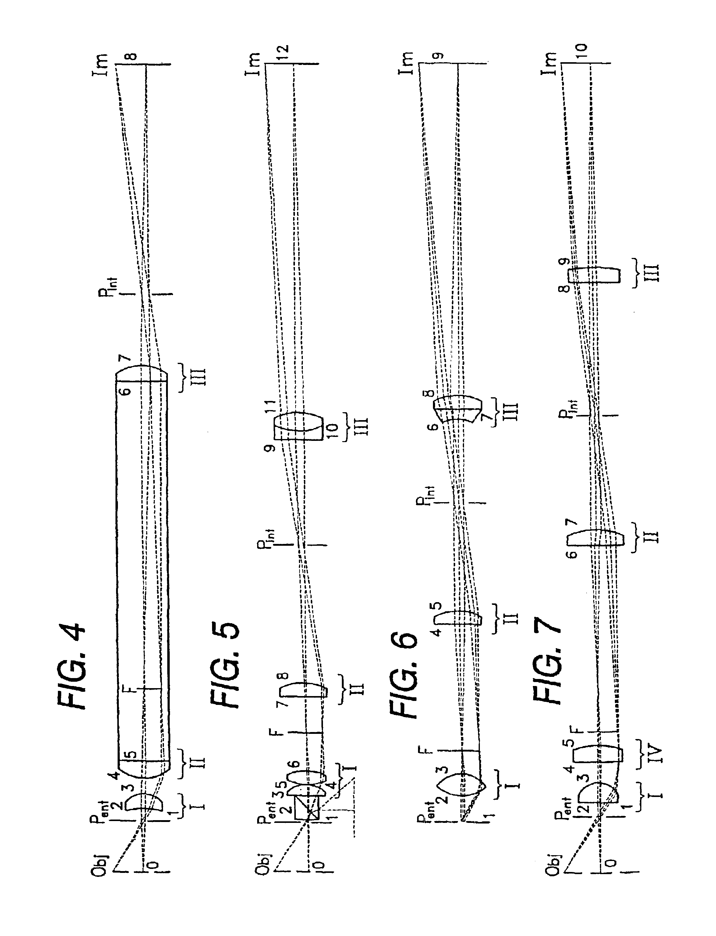
Exemplary embodiments 1-11, corresponding to FIGS. 2-12 described below, are standardized such that the objective and the first relay have a length of about 100 millimeters, and most have a nominal magnification of unity. In this way, the performance of Embodiments 1-11 can be conveniently compared. Embodiments with other magnifications, fields of view, numerical apertures, and with additional relays are presented in order to show that the general concept of the invention is effective over a wide range of applications. The embodiments described herein (1-18) use conventional, non-GRIN (gradient refractive index) lens elements, and thus each lens has a uniform refractive index, though other lens types may be used as well.

In FIGS. 1-18, the object and image planes are indicated by an ‘Obj’ and ‘Im,’ respectively. Intermediate focal planes and pupil planes are indicated at various points in the optical train by an ‘F’ and a ‘Pint’, respectively. Optical system features of the object pl...


PUM


Abstract

Optical systems (1-19) for endoscopes and the like are characterized by an integrated design in which the locations of the components and the aberration corrections are no longer tied to the optical functions of the objective (1-6) and the relays (7-19), and in which the relays may depart from symmetry. The power requirements can thus be shifted from one group to another, thereby reducing the overall power requirement. Moreover, the aberration correction can be shared between the optical group of the integrated system.

Description

FIELD OF THE INVENTIONThe present invention relates generally to optical lens system, and more particularly to lens systems suitable for endoscopes and the like.BACKGROUND OF THE INVENTIONIn endoscopy and related fields, such as borescopes and dental scopes, the complete optical system is thought of as consisting of four basic and separate optical functions. Those functions are, in sequence of the direction of the travelling light, as follows:(1) an objective which forms the first image of an object under surveillance,(2) a field lens which images the pupil of the objective onto the next image transfer lens,(3) an image transfer lens which reimages the first image onto the next field lens. The pupil and image transfer steps are repeated as often as is needed to obtain a desired tube length, and(4) a focusing lens which presents the final image to a sensor, such as a person's eye, a CCD camera, or a photographic film.This approach is the classical approach, which is appropriate for t...

Claims


Application Information

Patent Timeline
Patent Type & Authority Patents(United States)
IPC IPC(8): G02B23/24
CPCG02B23/2423
Inventor HOOGLAND, JAN
Owner RES CORP TECH INC
Why Eureka
Try Eureka