Tunable capacitor

a capacitor and capacitor technology, applied in the field of tunable capacitors, can solve the problem of relatively high parasitic resistance of capacitors and lower q

Inactive Publication Date: 2005-02-08
AGILENT TECH INC
View PDF2 Cites 60 Cited by
  • Summary
  • Abstract
  • Description
  • Claims
  • Application Information

AI Technical Summary

Problems solved by technology

Thus, one problem with conventional MEM tunable interdigitated capacitors is that such capacitors have a relatively high parasitic resistance that lowers the Q.

Method used


Image

  • Tunable capacitor
  • Tunable capacitor
  • Tunable capacitor

Examples


Embodiment Construction

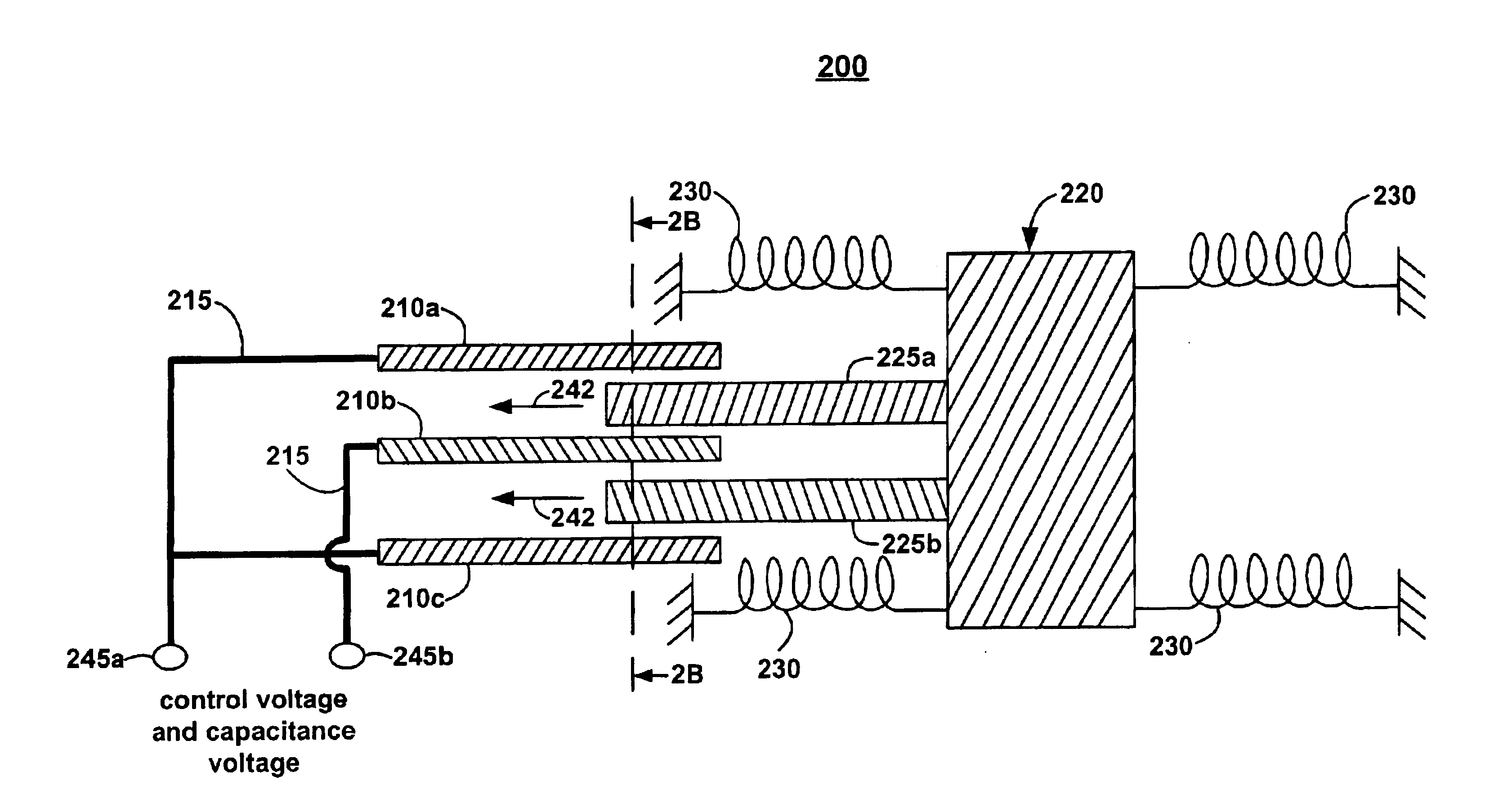
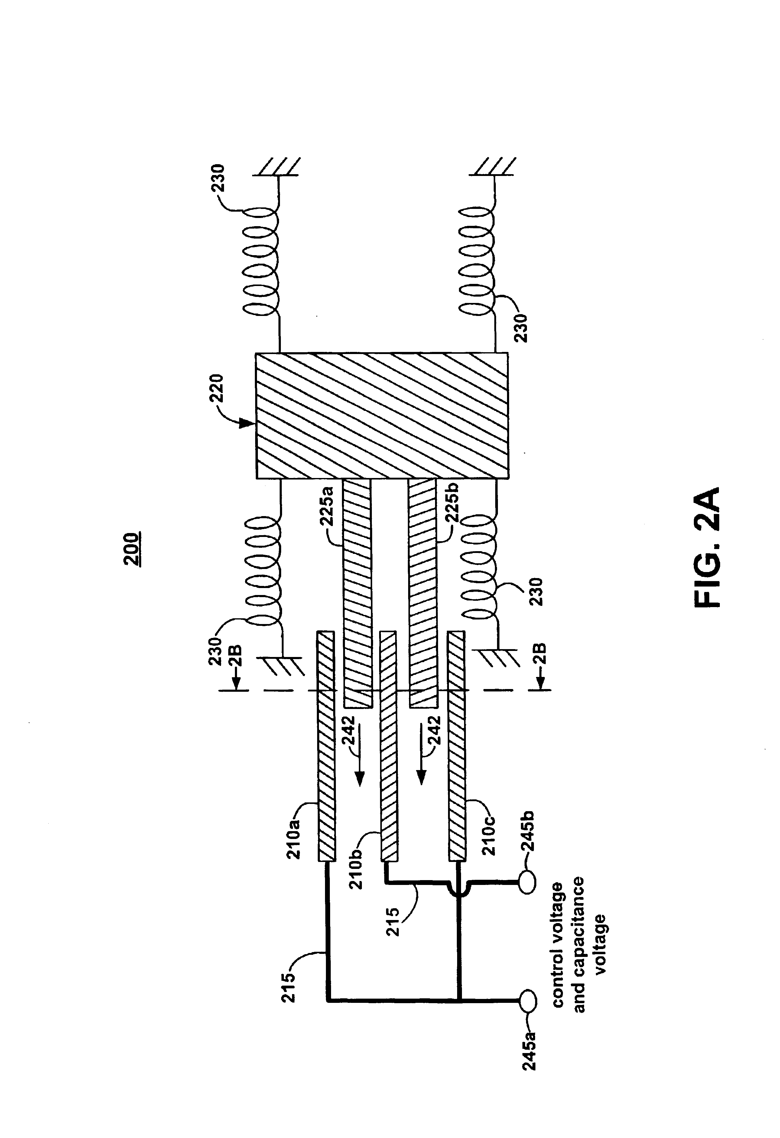
FIG. 2A illustrates an exemplary embodiment of a tunable interdigitated capacitor 200 in accordance with an embodiment of the present invention. The exemplary tunable interdigitated capacitor 200 has fixed fingers 210a-c, which serve as the electrodes of the tunable interdigitated capacitor 200. The exemplary tunable interdigitated capacitor 200 also has movable components 225a-b that are used to adjust the capacitance between fixed finger 210b and fixed fingers 210a and 210c. FIG. 2B is cross-sectional view of the tunable interdigitated capacitor 200 along the line 2B—2B in FIG. 2A.

Referring again to FIG. 2A, fixed fingers 210a and 210c, which constitute one electrode of tunable capacitor 200, are electrically connected to one terminal 245a. In a similar fashion, the other fixed finger 210b, which constitutes the other electrode of tunable capacitor 200, is electrically connected to the other terminal 245b. A combination of the control voltage and capacitance voltage is applied to ...


PUM

PropertyMeasurementUnit
widthaaaaaaaaaa
resistanceaaaaaaaaaa
dielectric constantaaaaaaaaaa

Abstract

A tunable capacitor. The tunable capacitor has a first fixed capacitor electrode and a second fixed capacitor electrode opposite to one another. The tunable capacitor also has a movable element formed of a conductive material. The movable element is moveable between the first fixed capacitor electrode and the second fixed capacitor electrode to adjust the capacitance between the first fixed capacitor electrode and the second fixed capacitor electrode.

Description

TECHNICAL FIELDEmbodiments in accordance with the present invention relate to the field of tunable capacitors. Specifically, embodiments in accordance with the present invention relate to a tunable capacitor having a high Q.BACKGROUND ARTMany applications incorporate a tunable integrated circuit capacitor. Micromachined electro-mechanical devices (MEMs) provide a way to construct a tunable capacitor within an integrated circuit. An important parameter for a capacitor is the quality factor (Q). To achieve a high Q, a capacitor should have a low parasitic series resistance, as given by the equation Q=1 / (2πfRC), where R is the parasitic series resistance. A high-Q capacitor is desirable in many applications. For example, low-noise radio frequency (RF) voltage controlled oscillators (VCOs) need a resonant device with a high Q because the phase noise of an oscillator is proportional to 1 / Q2, where Q is the overall Q of the resonator (W. P. Robins, “Phase Noise in Signal Sources: Theory a...

Claims


Application Information

Patent Timeline
Patent Type & Authority Patents(United States)
IPC IPC(8): H01G5/00H01G5/14
CPCH01G5/14
Inventor WILLIAMS, KIRT R.
Owner AGILENT TECH INC
Why Eureka
Try Eureka