Compact converter station

a converter station and compact technology, applied in the field of converter stations, can solve the problems of high cost and associated additional cost, and achieve the effect of more cost-effectiveness

Inactive Publication Date: 2005-02-08
SIEMENS AG
View PDF3 Cites 27 Cited by
  • Summary
  • Abstract
  • Description
  • Claims
  • Application Information

AI Technical Summary

Benefits of technology

In another embodiment of the invention, the transformer units do not have additional winding taps or additional windings for a tertiary AC voltage. Transformers such as these, are in particular, more cost-effective and, furthermore, have advantages with regard to harmonic filtering by the filter units.
At least one internal fire-resistant fire barrier wall is advantageously provided in the converter building and is arranged at a distance from an outside wall, forming a ventilation shaft, with an inner ventilation gap being provided in the fire barrier wall and an outer ventilation gap being provided in the outside wall. The ventilation gaps are arranged at mutually different wall heights in order to prevent flames from emerging from the outside wall. According to this embod

Problems solved by technology

The described design of a converter station is subject to the disadvantage that implementation of the design would be costly and would lead to a physically interleaved building in order to accommodate the conver

Method used


Image

  • Compact converter station
  • Compact converter station
  • Compact converter station

Examples


Embodiment Construction

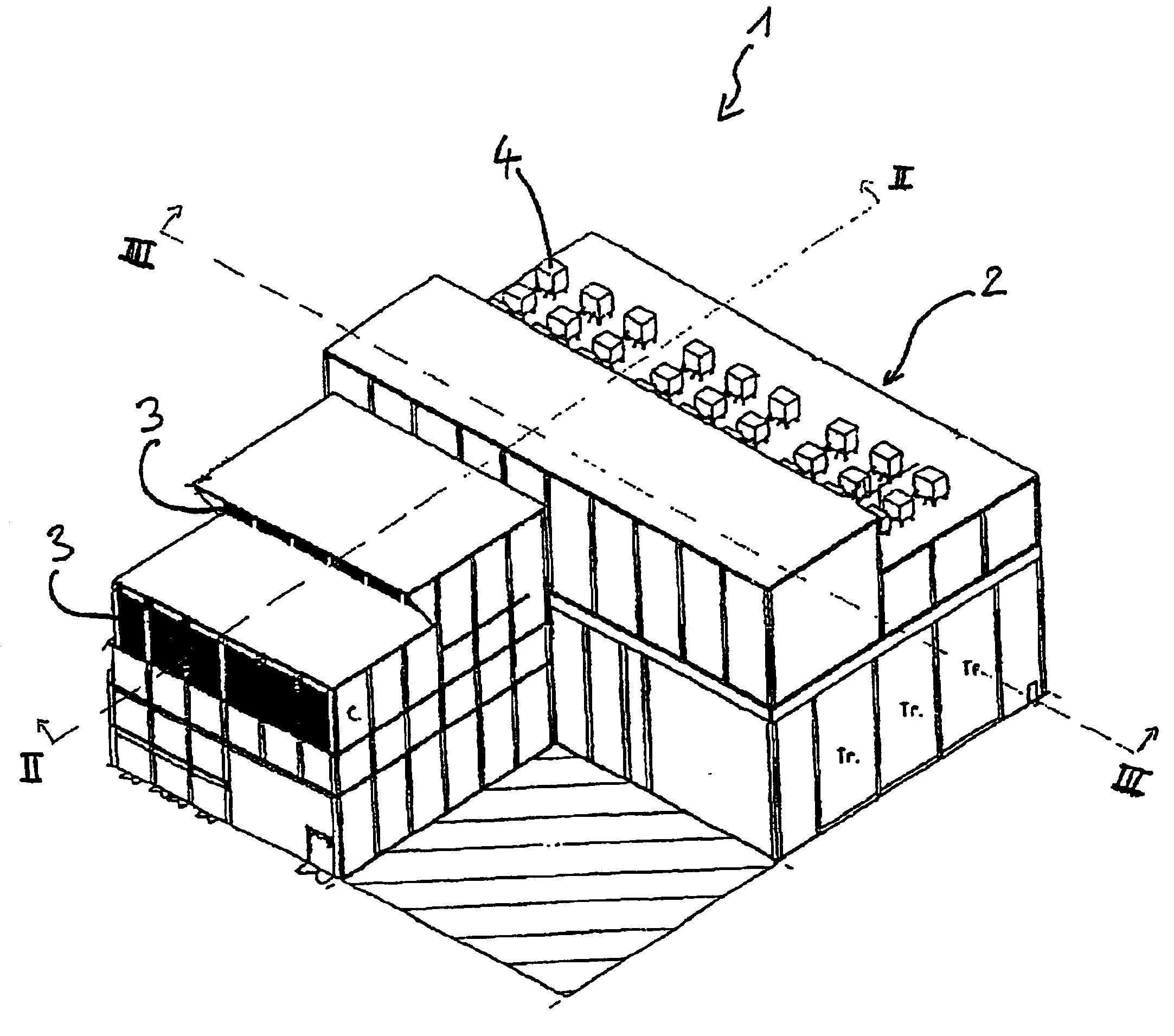
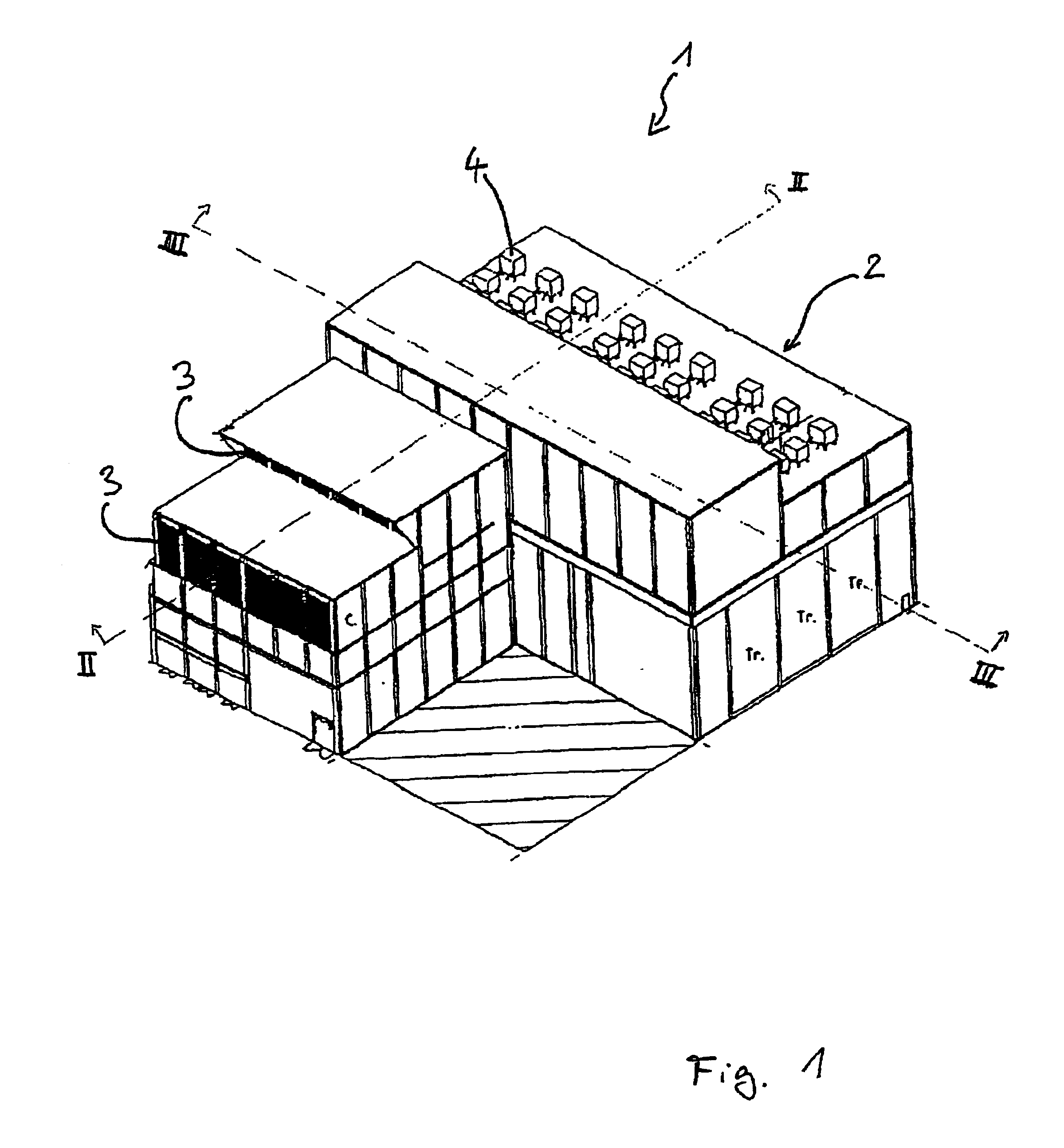
FIG. 1 shows an exemplary embodiment of the converter station 1 according to the invention, in the form of a three-dimensional illustration. This illustration shows in particular that the components are arranged in or on a closed converter building 2, which has a number of floors. Ventilation openings 3 can be seen in the front region of the building 2, while resistors 4 which are arranged in the rear region on the roof of the converter building 1 are illustrated in the figures.

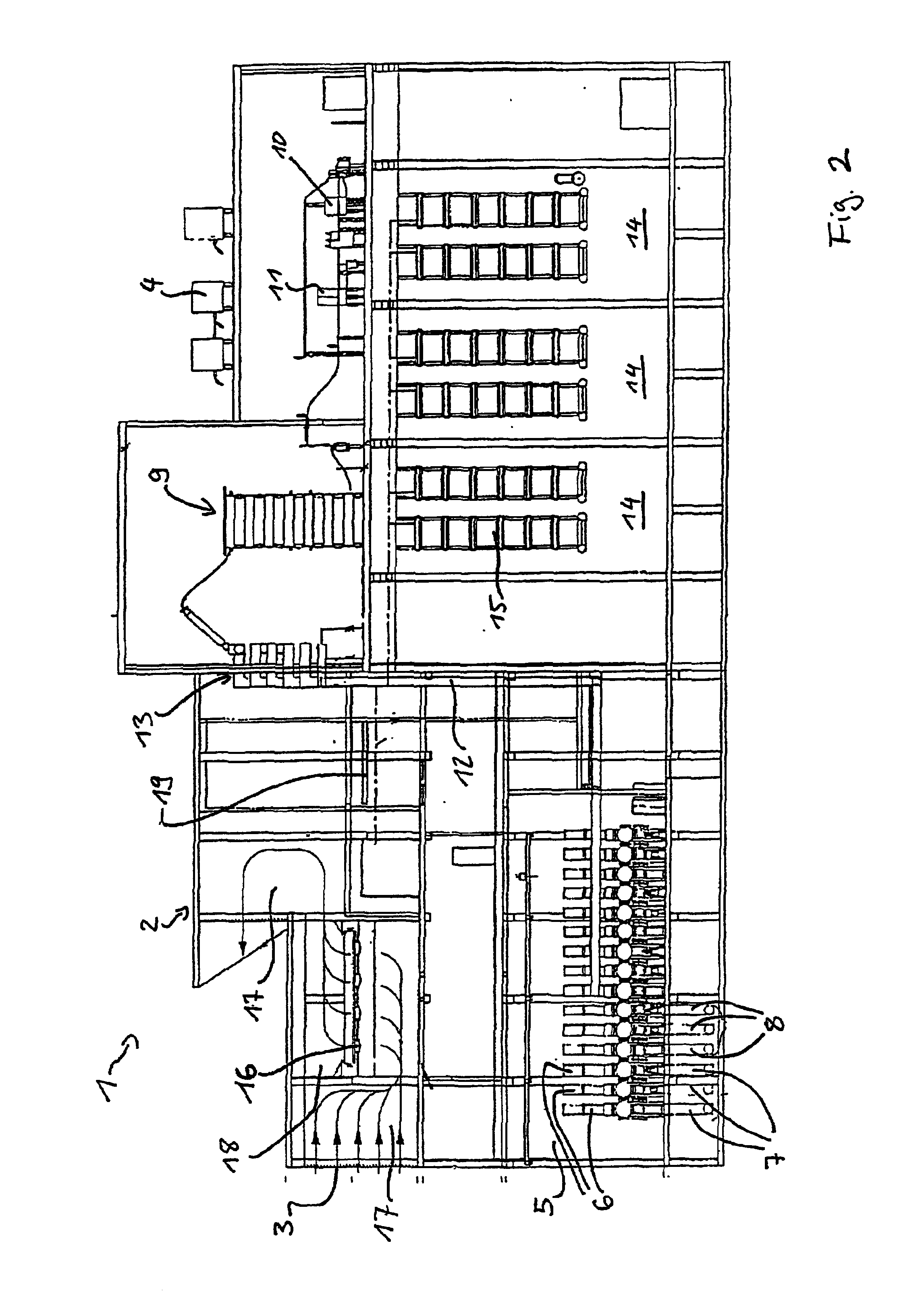
FIG. 2 shows the converter station 1 in a view sectioned along the line II in FIG. 1. Gas-insulated feeder units 6 are arranged in a switching area 5 in the lower first floor. Sulfahexafluoride is used as the inert gas. Each phase in the first three-phase feeder unit 6 is connected to an AC cable 7, which is designed for feeding the power that is transmitted by means of high-voltage direct current to the converter station 1 to an AC network, which is not illustrated. However, the energy flow direction may als...


PUM


Abstract

In order to provide a converter station for a high-voltage DC connection between two three-phase AC voltage networks, having a converter building which has a number of floors, and in which transformer units, converter devices, filter units, a gas-insulated switchgear assembly with feeder units, at least one cooling system, a DC cable pot head for electrical connection of a high-voltage cable carrying direct current, a smoothing reactor and gas-insulated busbars for electrical connection of these components are arranged, while maintaining its compact design and the arrangement of its components in a closed building, whose cost is low and which has a physically simple design, the invention proposes that the DC cable pot head and the smoothing reactor are arranged on the same floor as the converter valves and are electrically connected to one another via an air-insulated connecting device, with an air-insulated isolating switch being provided in order to produce an isolating gap between the DC cable pot head and the smoothing reactor.

Description

TECHNICAL FIELD OF THE INVENTIONThe invention relates to a converter station for a high-voltage DC connection between two three-phase AC voltage networks.BACKGROUND OF THE INVENTIONA converter station is known from the lecture “A study of + / −500 kV, 2400 MW compact converter station”, whose authors were D. E. Fletcher, D. L. Gordon, R. E. Harrison, M. A. Lebow and R. Mauro at the “IEE International Conference on AC and DC Power Transmission” on Sep. 17-20, 1991, and was published in London, United Kingdom, under the ISBN Number 0-85296-517-6, in 1991, on pages 165-170 of Volume 345 of “AC and DC Power Transmission”. The design described there for a compact converter station develops a concept for the accommodation of a converter station for high-voltage DC transmission in a closed multistory building. The converter station has converter valves which extend over a number of floors and are mounted in a suspended fashion in valve halls. Filter units are provided on the top floor of the...

Claims


Application Information

Patent Timeline
IPC IPC(8): H02J3/36
CPCH02J3/36Y02E60/60
Inventor ANHEUER, MATHIASFRIEDRICH, KURTSOERANGR, DAG
Owner SIEMENS AG
Why Eureka
Try Eureka