Radiation therapy dosimetry quality control process

a technology of quality control and radiation therapy, applied in the field of radiation therapy dosimetry quality control process, can solve the problems of individual mistakes, errors in the final dose of the patient, and possible errors, and achieve the effect of achieving more accurate results

Inactive Publication Date: 2005-02-08
LIFELINE SOFTWARE INC
View PDF6 Cites 58 Cited by
  • Summary
  • Abstract
  • Description
  • Claims
  • Application Information

AI Technical Summary

Problems solved by technology

Inherent in any activity carried out, by human beings in particular, is the possibility of errors.
These errors may involve a misunderstanding between the physician prescribing the radiation dose and the technician who generally operate, the treatment planning system to develop a plan.
Individuals might make mistakes in the generation of the plan, such as setting the wrong distance for a field as one example.
Any error in the weighting of these fields, or in the modifying devices 32 placed in the fields 34, will lead to an error in the final dose the patient receives.
This lengthy and complex process has multiple opportunities for errors to be committed by persons or machines.
However detailed information about the dose actually delivered to the patient is hard to come by, as it is difficult to make measurements within the patient's body.
Yet without a feedback mechanism for the entire treatment planning and delivery process, failure to detect a problem with any component or underlying concept wilt most likely go unnoticed.
However, the measurement at one or a few points does not demonstrate how the effects of all the treatment beams are adding up, nor show the dose to the target volume or critical structures.
Making measurements inside the patient is generally limited to a few points if there is a cavity available and is an invasive procedure.
However, the measured intensity of each exit ray cannot be used directly as radiation will also reach the same detector that has scattered from within the patient's body and this scatter dose contributes to the measured signal.
Such problems are difficult although not impossible to solve.
Further, the computation of the scatter component in itself, given a known beam, is a difficult problem.
These difficulties combined with the back ray tracing through the patient are very likely to result in large uncertainties in the final result that will greatly reduce the reliability and therefore usefulness of the final result for verification purposes.
Systems which intend to compute the dose distribution from measured exit dose have yet to demonstrate an accuracy to be of sufficient use.

Method used


Image

  • Radiation therapy dosimetry quality control process
  • Radiation therapy dosimetry quality control process
  • Radiation therapy dosimetry quality control process

Examples


Embodiment Construction

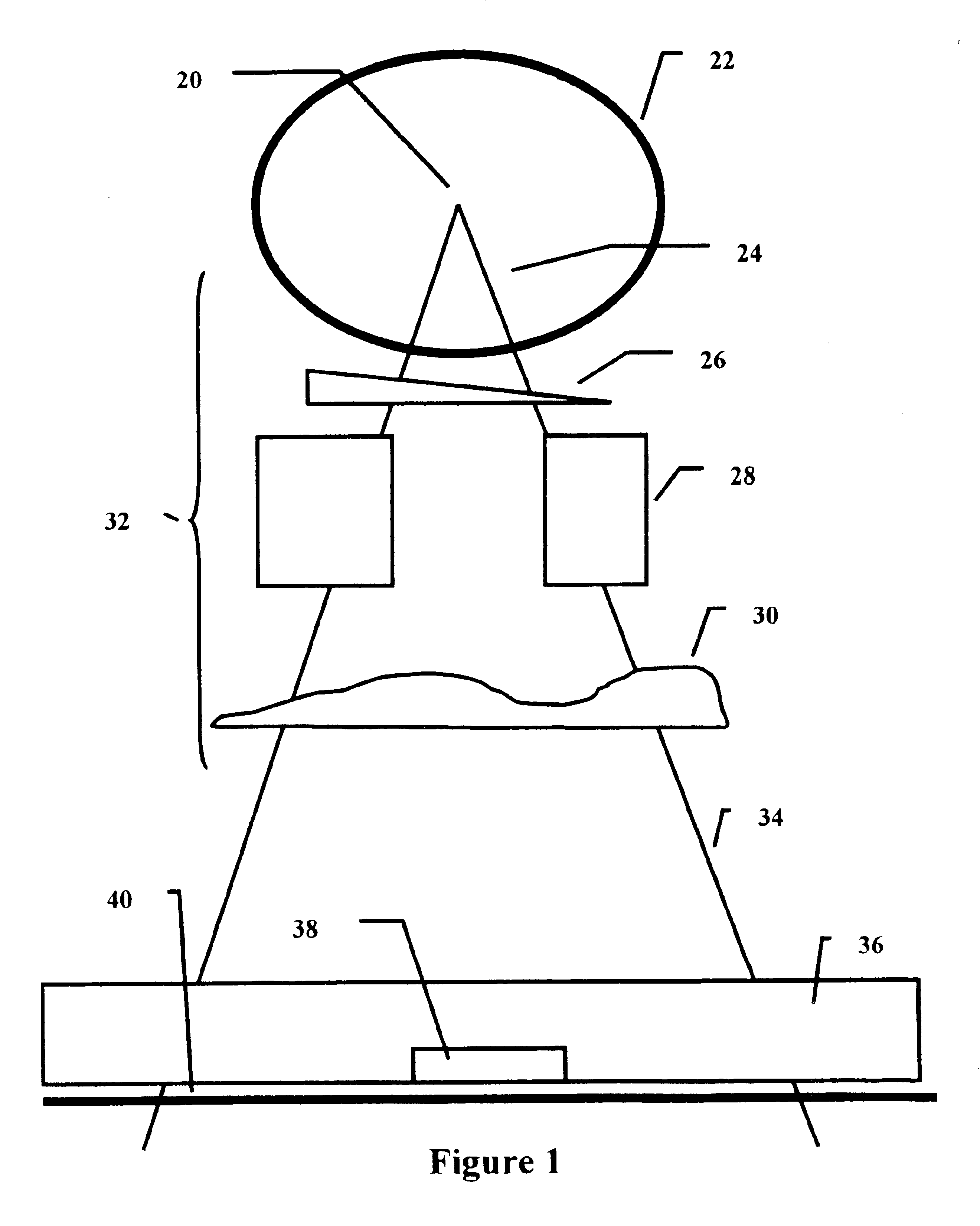
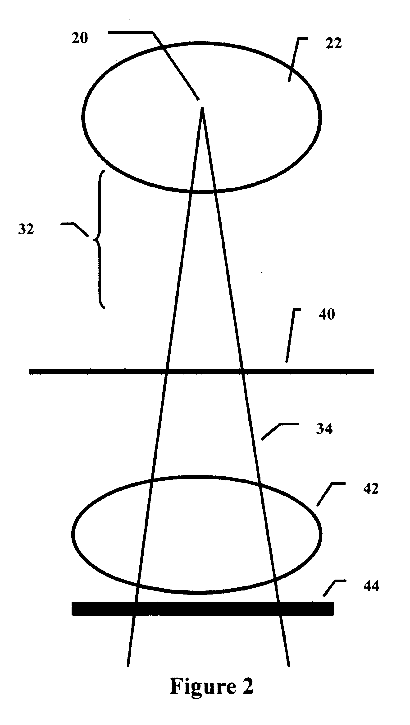
The process described below is for the purpose of verifying and testing the intended treatment plan to be applied to a patient using external beam radiation. It is assumed that a radiation therapy treatment plan has been developed employing current standard state of the art treatment planning techniques represented by 46 in FIG. 3. These techniques generally involve obtaining cross sectional images of the patient's body 42 in FIG. 2 with CT scanners or other means, and generating a treatment plan using computerized treatment planning systems provided for that purpose. CT is generally the imaging modality preferred due to its geometric accuracy and that CT pixel numbers can be converted to electron density needed by dose algorithms. MRI and mechanical means for obtaining cross sectional outlines are also sometimes employed.

This present invention consists of providing a more complete feedback mechanism whereby the dose to the patient volume can be assessed in 2d planes and 3d perspect...


PUM


Abstract

A treatment verification process for radiation therapy consisting of measuring each of the radiation beams that are to be applied to the patient by making a calibrated image of the field for each beam. The measured beams are then processed and converted to relative monitor units. Software like a treatment planning system is then used to compute the dose to the patient for comparison with the intended treatment prescription.

Description

BACKGROUND OF THE INVENTION1. Technical FieldThis invention concerns a process for verification of the radiation dose delivered to patients undergoing radiation therapy.2. Prior ArtMedical linear accelerators and Cobalt 60 external beam units {represented by 22 in FIGS. 1 and 2) are well known machines used to treat human beings for cancer. The radiation source in these machines are generally mounted in a gantry that can rotate around the patient. A target area within the patient may therefore be irradiated from different directions. Before irradiation the treatment is typically planned on a computer using algorithms that can simulate the radiation beams and allow the medical personnel to design the treatment beam positions and field modifiers that may be placed within the treatment beams.Inherent in any activity carried out, by human beings in particular, is the possibility of errors. These errors may involve a misunderstanding between the physician prescribing the radiation dose a...

Claims


Application Information

Patent Timeline
Patent Type & Authority Patents(United States)
IPC IPC(8): A61N5/10
CPCA61N5/1048A61N5/1075A61N5/1071
Inventor RENNER, WENDEL DEAN
Owner LIFELINE SOFTWARE INC
Why Eureka
Try Eureka