
Solenoid valve with terminal box

a terminal box and valve body technology, applied in the direction of valve operating means/releasing devices, service pipe systems, transportation and packaging, etc., can solve the problems of complex assembly operation, large number of independent parts to be handled, etc., and achieve the effect of simple structur

Inactive Publication Date: 2005-02-15
SMC CORP
View PDF8 Cites 13 Cited by
  • Summary
  • Abstract
  • Description
  • Claims
  • Application Information

AI Technical Summary

Benefits of technology

It is a technical object of the present invention to enable a terminal box having various parts required to energize an exciting coil to be reliably and detachably mounted to a solenoid valve with a simple structure.
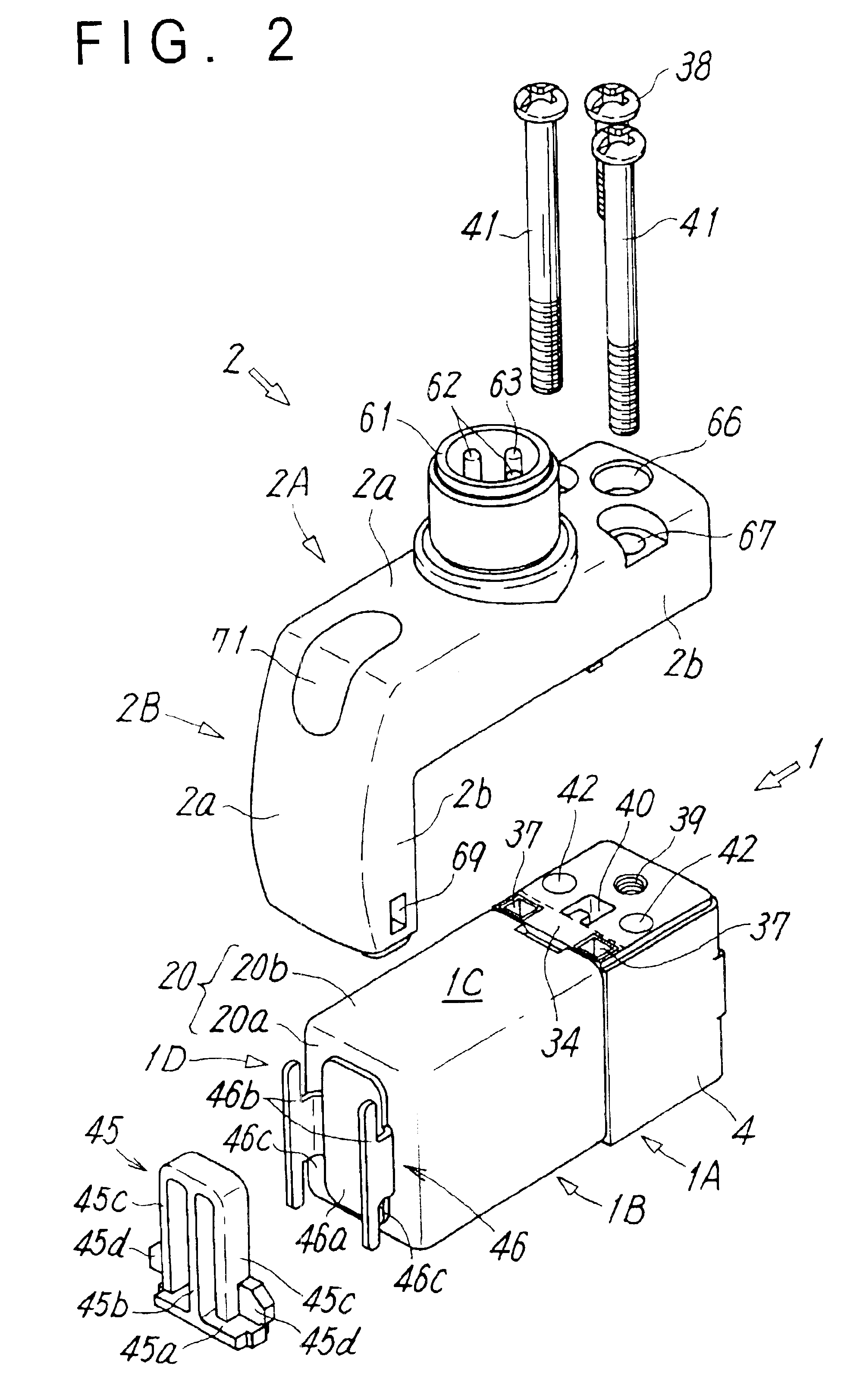
Because the invention has the above structure, the terminal box can be mounted to the solenoid valve by pushing the first portion of the terminal box against the first mounting face of the solenoid valve, inserting the connecting terminals on the first portion into the terminal holes on the first mounting face to connect the connecting terminals to the coil terminals, locking the locking holes formed in the second portion of the terminal box to the elastic clip on the second mounting face of the solenoid valve, and fixing the first portion to the first mounting face with the fixing screw in this state. By only detaching the fixing screw to cancel locking of the elastic clip, the whole terminal box can be easily detached from the solenoid valve. Because the terminal box is formed into the substantially L-shaped bent form, the parts such as the connecting terminals and connectors which are required for electric connection to the solenoid valve are mounted to the first portion, and mechanisms required for locking to the solenoid valve are provided to the second portion, the terminal box can be formed into an extremely simple and rational design structure.
As described above, because the printed board, the indicating lamp, and the electronic components as a whole are encapsulated into the transparent resin and the peripheries of the terminal holes into which the connecting terminals are fitted are sealed with the gasket, airtightness and electrical insulation of the terminal box and airtightness of the electric connection portion can be improved with an extremely simple structure.

Problems solved by technology

Therefore, a plurality of independent parts must be handled and an assembly operation and the like are relatively complicated.

Method used


Image

  • Solenoid valve with terminal box
  • Solenoid valve with terminal box
  • Solenoid valve with terminal box

Examples


Embodiment Construction

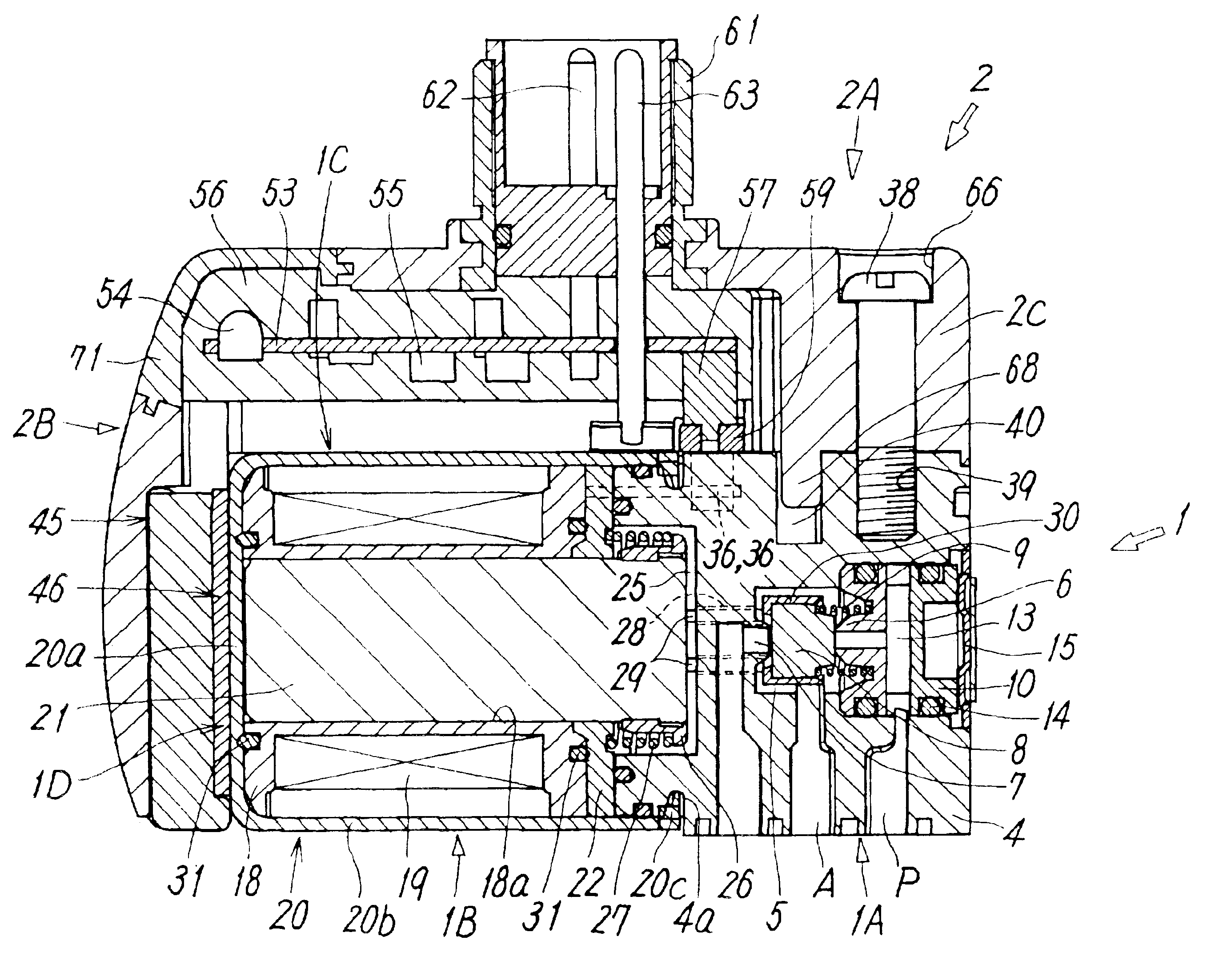
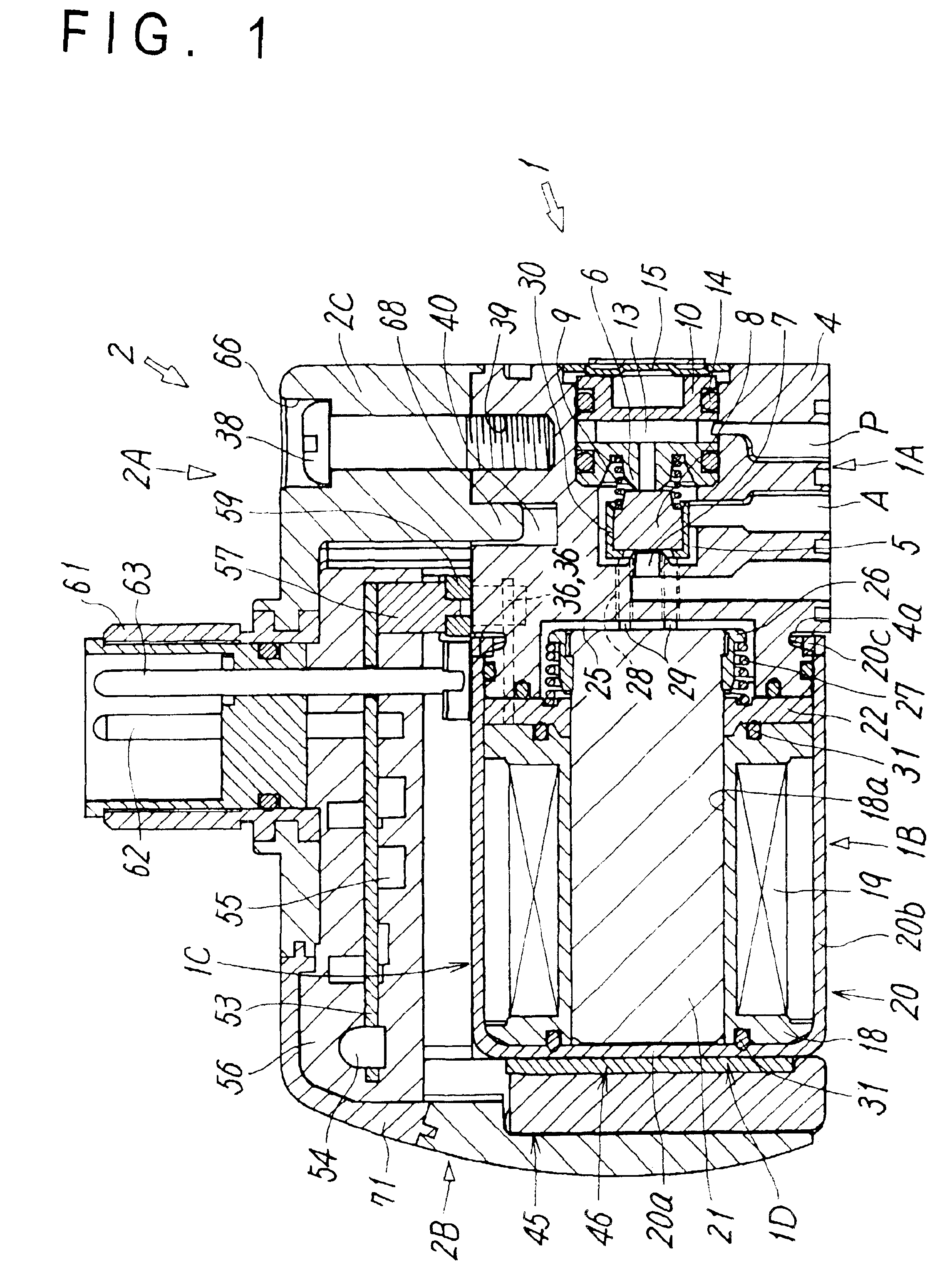
FIG. 1 shows a representative embodiment of a solenoid valve with a terminal box according to the present invention. In the drawings, a reference numeral 1 designates a solenoid valve and a reference numeral 2 designates a terminal box 2 detachably mounted to the solenoid valve.

The solenoid valve 1 is a three-port direct-acting solenoid valve and includes a valve main body portion 1A having a valve member 8 for selecting a fluid flow path and a solenoid operating portion 1B for driving the valve member.

The valve main body portion 1A has a housing 4 having a rectangular sectional shape. In a side face of the housing 4, a supply port P, an output port A, and a discharge port R are provided. Provided in the housing 4 are a valve chamber 5 with which the respective ports P, A, and R communicate, a supply valve seat 6 formed in a position with which the supply port P communicates in the valve chamber 5, and a discharge valve seat 7 formed in a position with which the discharge port R com...


PUM


Abstract

A solenoid valve includes a first mounting face and a second mounting face for mounting of a terminal box. The first mounting face is formed with terminal holes in which coil terminals are housed and a screw hole for fixing. The second mounting face is provided with an elastic clip having hooks. The terminal box is in a substantially L shape. A first portion of the terminal box is provided with connecting terminals to be connected to the coil terminals, a connector to be brought into continuity with the connecting terminals, and a printed board mounted with an indicating lamp and electric components. A second portion of the terminal box is provided with locking holes into which the hooks of the elastic clip are locked.

Description

TECHNICAL FIELDThe present invention relates to a solenoid valve with a terminal box for energizing an exciting coil.PRIOR ARTIn general, a solenoid valve includes a valve main body portion having a valve member for selecting a fluid flow path and a solenoid operating portion having an exciting coil and a movable core and energizes the exciting coil in the solenoid operating portion to thereby operate the movable core and to directly drive the valve member with the movable core or indirectly drive the valve member through another member. For energizing the exciting coil, a receiving connector is provided in a proper position of the solenoid valve and the connector and a coil terminal extending from the exciting coil are connected by various means.For example, disclosed in Japanese Utility Model Registration No. 2607670 is one in which a terminal box is formed by fixing a cover to an outer face of a solenoid portion of a solenoid valve and mounting a case to the cover, a printed boar...

Claims


Application Information

Patent Timeline
IPC IPC(8): F16K31/06H01F5/04H01F5/00H01F7/06H01F27/04H01F27/02F16K31/02
CPCF16K31/0675H01F5/04H01F7/06H01F2007/062H01F27/04Y10T137/8158F16K31/02
Inventor MIYAZOE, SHINJI
Owner SMC CORP
Learn More