
Hydrodynamic pressure bearing, spindle motor in which it is utilized, and disk-drive device furnished with the spindle motor

a technology of hydraulic pressure bearings and bearings, which is applied in the direction of bearings, shafts and bearings, rotary bearings, etc., can solve the problems of inadequate supply of oil to the bearing sections under high rpm conditions, and achieve the effect of sealing strength

Inactive Publication Date: 2005-02-15
NIPPON DENSAN CORP
View PDF8 Cites 11 Cited by
  • Summary
  • Abstract
  • Description
  • Claims
  • Application Information

AI Technical Summary

Benefits of technology

An object of the present invention is to realize higher-rpm-handling hydrodynamic bearings with which sealing strength may be fortified and the supplying of oil to the thrust bearing sections may be stabilized, and moreover in which the volume within the taper seal sections is enlarged to enable a sufficient amount of oil to be retained therein.
Another object is to realize a spindle motor that enables preventing oil leakage even due to high-speed rotation.
A different object of the present invention is to realize a disk-drive device that makes it possible to drive data recording disks at high speed, and is of superior reliability and durability.
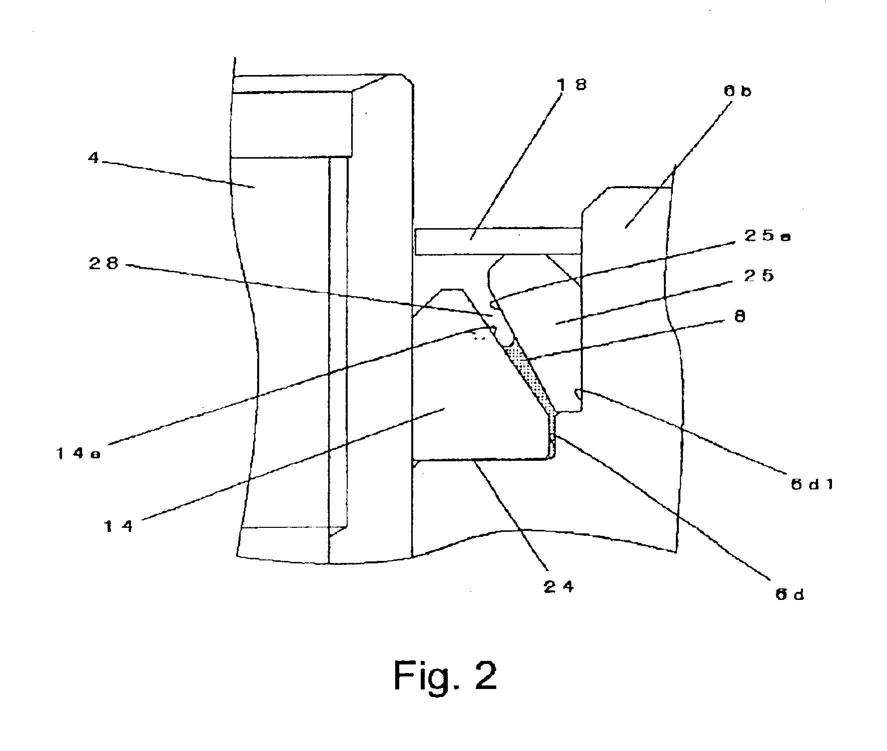
Lubricant may be retained continuously between the outer periphery of the thrust plate and the thrust bearing section with this hydrodynamic bearing even during high-speed rotation, without the lubricant being torn off under centrifugal force from the outer circumferential surface of the thrust plate. The fact, furthermore, that the interface of the lubricant heads in a sloping direction with respect to the rotational center axis means that centrifugal force acts in a direction in which it presses down on the lubricant interface, whereby the seal strength is more highly sustained.
A hydrodynamic bearing of this sort is also utilized to support rotation of the rotor hub in a spindle motor of the present invention. Not only does this consequently enable high-speed, high-precision rotational support, but also the fact that incidents of seizure in the bearing sections are prevented enables rendering the spindle motor superior in reliability and durability.
In addition, a disk-drive device of the present invention drives data-recording disks by means of a spindle motor furnished with the foregoing hydrodynamic bearing—which consequently not only enables high speed, high-precision rotational support, but also makes for a disk-drive device rendered superior in reliability and durability.

Problems solved by technology

Lack thus of sufficient capacity secured to accommodate the greater amount of oil flow at higher rpm will be cause for concern that oil will flow out to the bearing exterior.
The taper seal sections should then serve, as noted above, in a capacity of supplying oil to the bearing sections when the amount of oil retained therein has decreased; but oil becoming stuck on the inner circumferential surface of the rotor by the action of centrifugal force spoils the continuity of the oil, meaning that the supply of oil to the bearing sections under high rpm conditions will become inadequate.
Depletion in the amount of oil retained in the thrust bearing sections impairs the bearing rigidity, which not only destabilizes rotational support, but also gives rise to contact and slippage between the thrust plate and the rotor occurs, producing seizure.

Method used


Image

  • Hydrodynamic pressure bearing, spindle motor in which it is utilized, and disk-drive device furnished with the spindle motor
  • Hydrodynamic pressure bearing, spindle motor in which it is utilized, and disk-drive device furnished with the spindle motor
  • Hydrodynamic pressure bearing, spindle motor in which it is utilized, and disk-drive device furnished with the spindle motor

Examples


Embodiment Construction

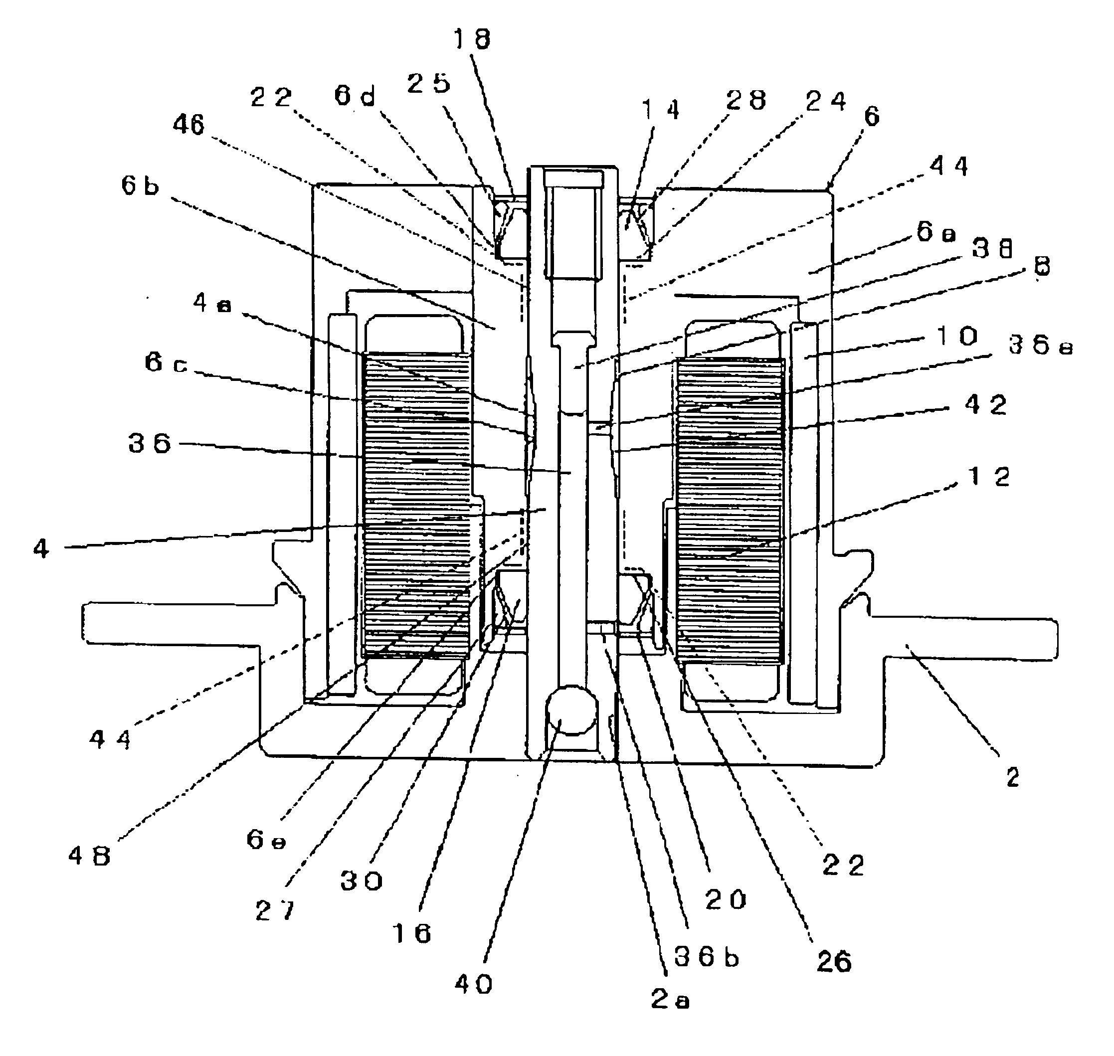
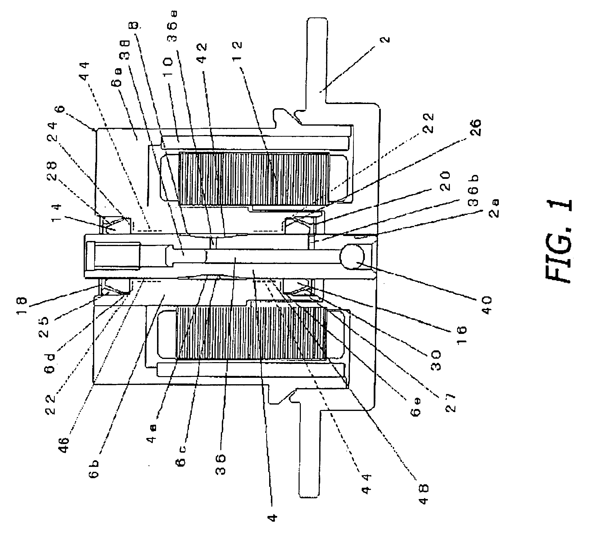
Embodiments relevant to the present invention of a hydrodynamic bearing, a spindle motor in which the hydrodynamic bearing is utilized, and a disk-drive device equipped with the spindle motor will be explained in the following with reference to FIGS. 1 through 3; the present invention is not, however limited to the embodied examples set forth below.

The spindle motor represented in the figures is furnished with a bracket 2, a shaft 4 the exterior of one end of which is fixedly fitted into a central opening 2a in the bracket 2, and a rotor 6 rotative relative to the shaft 4. The rotor 6 is furnished with a rotor hub 6a on the outer periphery of which storage disks (illustratively represented as data-recording disks 53 in FIG. 3) are loaded, and a sleeve 6b disposed along the inner periphery of the rotor hub 6a and axially supported by the shaft 4 via a micro-gap in which lubricant 8 is retained. Rotor magnets 10 are fastened to the inner periphery of the rotor hub 6a by adhesive means...


PUM


Abstract

Spindle-motor hydrodynamic bearing configuration having conical taper seals on the thrust-bearing ends. The spindle motor shaft is supported in a bore through the rotor by neighboring radial and thrust hydrodynamic bearings constituted through radial micro-gaps cylindrically between the shaft and rotor, axial micro-gaps between thrust plates on either shaft end and recesses endwise in the rotor bore, dynamic-pressure-generating grooves in the micro-gap forming surfaces, and lubricant retained continuously in the radial and axial micro-gaps. The thrust plates are at least partially conical, tapering axially outward. A ring fitted in each rotor bore recess has a conical inner peripheral surface corresponding to the opposing conical surface of the thrust plate, forming a taper seal sloped with respect to the rotational axial center of the motor. The gap clearance dimension gradually expands heading axially outward, wherein the lubricant forms an axial-end gas-liquid interface to function as a taper seal.

Description

BACKGROUND OF INVENTION1. Technical FieldThe present invention relates to hydrodynamic pressure bearings, to spindle motors in which such bearings are utilized, and to disk-drive devices furnished with such spindle motors. The invention in particular relates to hydrodynamic pressure bearings capable of handling high rpm, spindle motors in which they are utilized, and disk-drive devices furnished with the spindle motors.2. Description of the Related ArtThe rotor in a spindle motor is rotatively supported along its axis by bearing means in a configuration such as disclosed for example in U.S. Pat. No. 5,558,445. This conventional spindle motor comprises a pair of thrust plates disposed on the upper and lower portions of a stationary shaft in its axial direction. A radial bearing section located between the pair of thrust plates is constituted by dynamic-pressure-generating striations formed between the outer circumferential surface of the stationary shaft and, opposing the outer circu...

Claims


Application Information

Patent Timeline
IPC IPC(8): F16C33/04F16C33/10F16C33/74F16C33/72F16C17/00F16C17/10
CPCF16C17/107F16C33/74F16C33/107F16C33/745F16C2370/12
Inventor NISHIMURA, HIDEKISHIDA, KUNIHIROYAMAUCHI, WATARU
Owner NIPPON DENSAN CORP
Learn More