Brackets and methods for holding wires utilizing magnetic force

Active Publication Date: 2005-02-15
R & B ENTERPRISES
View PDF27 Cites 27 Cited by
  • Summary
  • Abstract
  • Description
  • Claims
  • Application Information

AI Technical Summary

Benefits of technology

It is yet another object of the present invention to provide such novel brackets that are easily installed and removed and that are moveable and reusable to adapt to new configurations of the wire routing and to facilitate the organization and separation of wires during the wiri

Problems solved by technology

The wires can be left dangling in locations where it is impossible and/or undesirable to mount a permanent clip because of moving parts inside, such as on a combine, or when a metal surface may be too thin to support drilled holes or too dense to drill holes for permanent mounting.
When pulling a boat trailer or other trailer, wires often are left hanging as the trailer is temporarily wired to the pulling vehicle, and the wires can become tangled or can be damaged by road debris.
On truck box frames, the wire routing is difficult because the frame can be on different levels and the surfaces available for mounting the wire can be non-planar or irregu

Method used


Image

  • Brackets and methods for holding wires utilizing magnetic force
  • Brackets and methods for holding wires utilizing magnetic force
  • Brackets and methods for holding wires utilizing magnetic force

Examples


Embodiment Construction

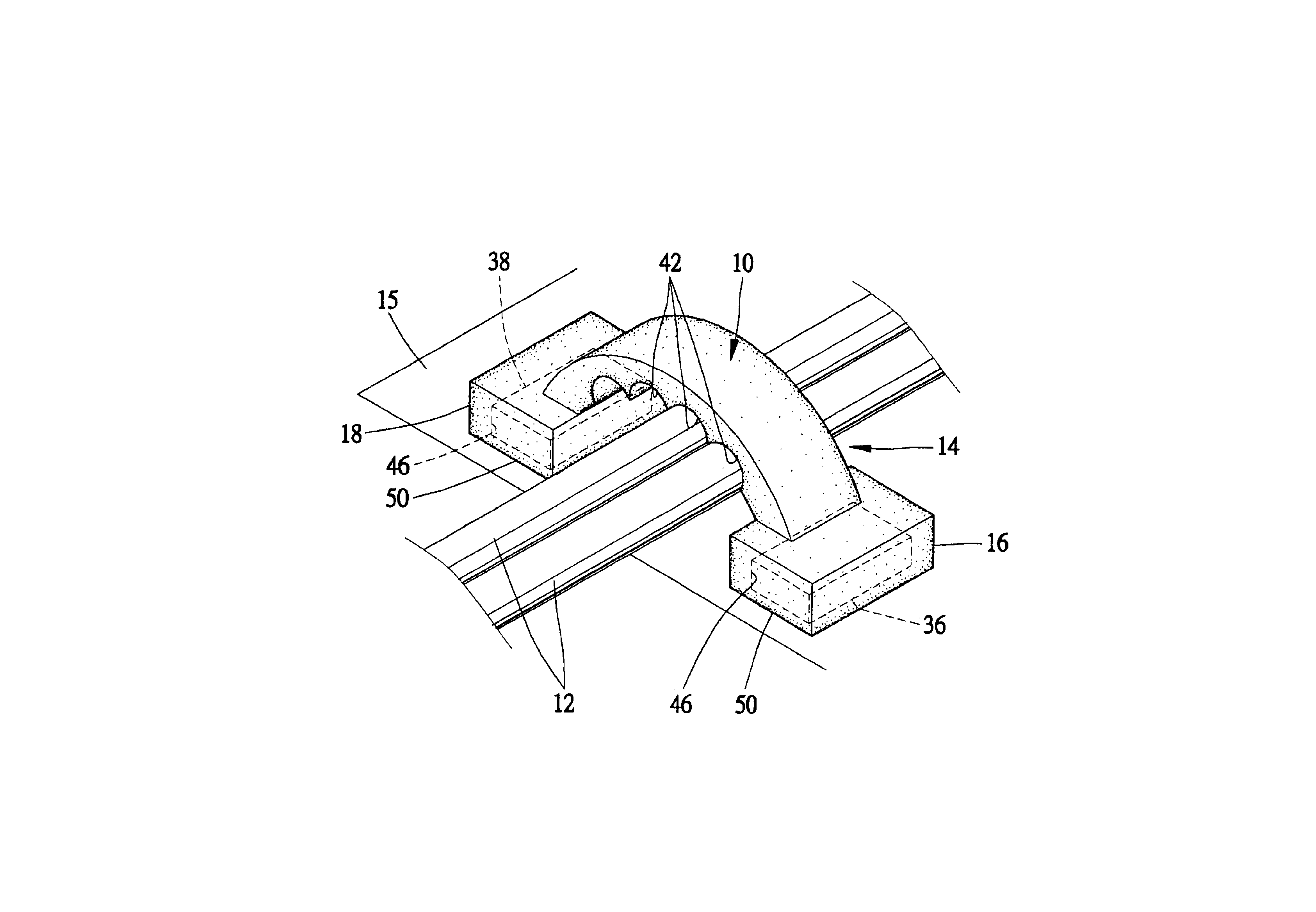
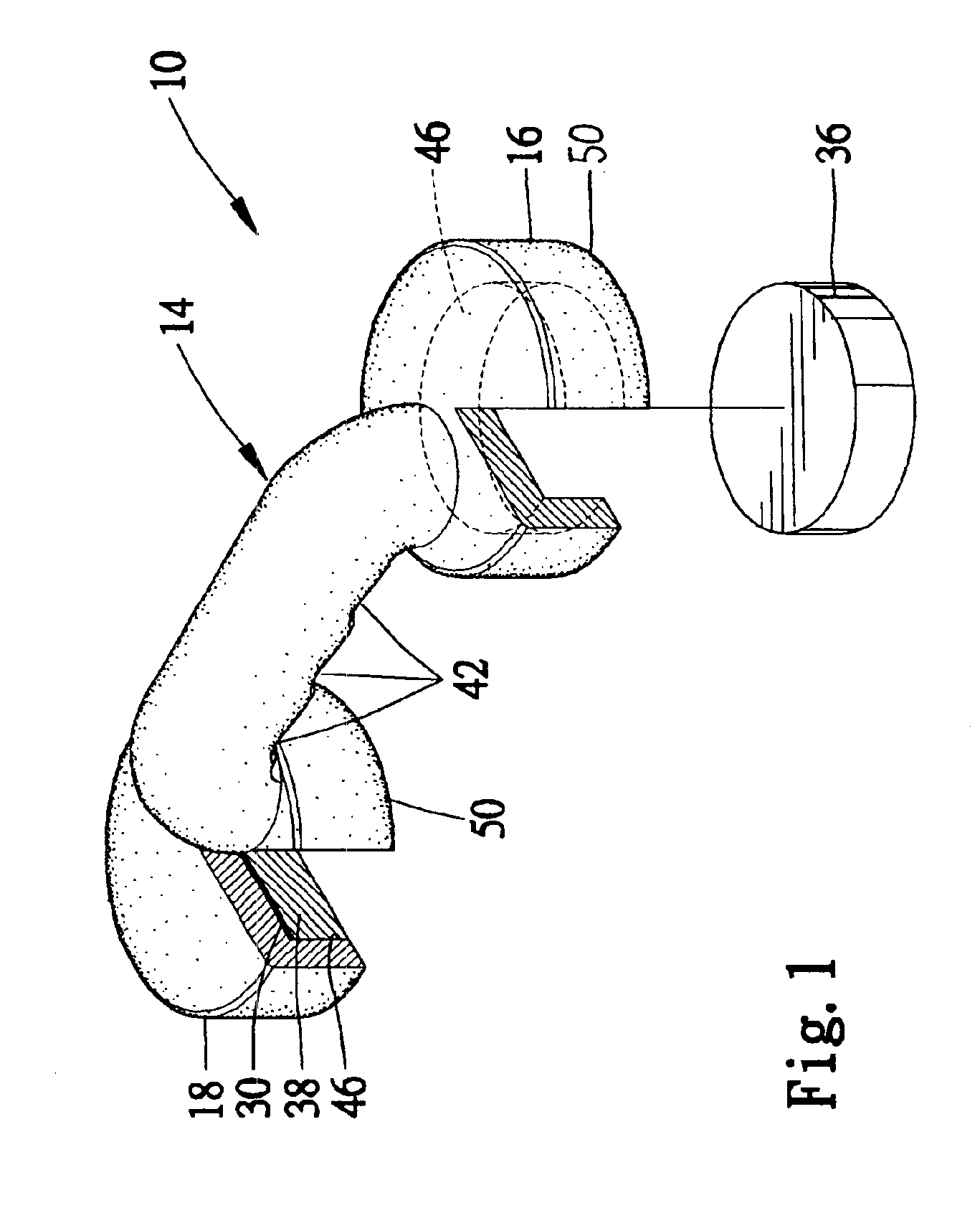
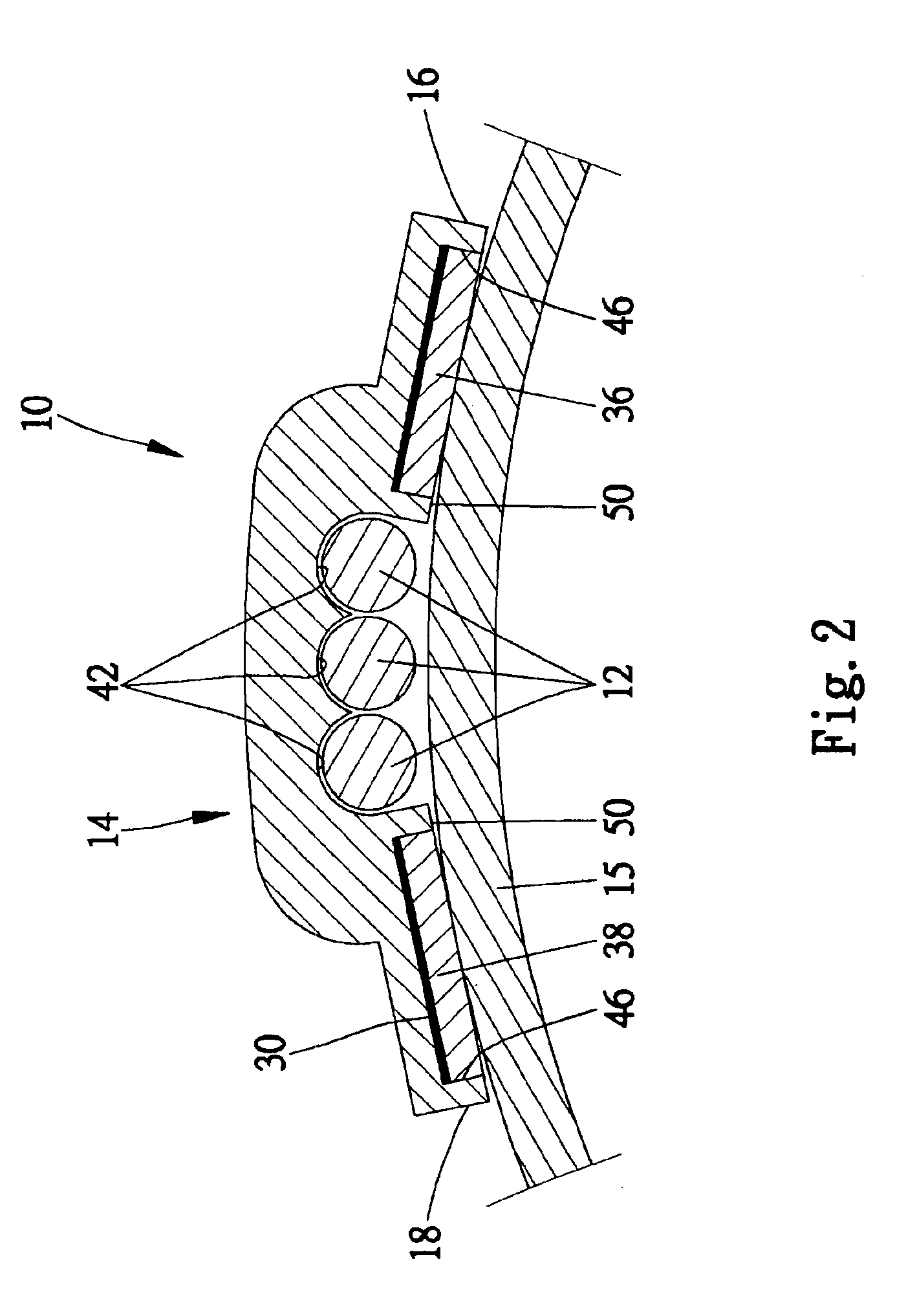
Brackets for holding wires adjacent to a magnetic surface utilizing magnetic force, constructed and utilized in methods according to the preferred teachings of the present invention, are shown in the drawings and generally designated 10. The magnetic surface 15 could be of a variety of forms including, but not limited to, metal, paneled metal, plastic coated metal, continuous or non-continuous, or planar or non-planar. Examples of continuous magnetic surfaces 15 are railings, steel siding and steel rain gutters on a house, and examples of non-continuous magnetic surfaces 15 are nails or similar magnet attractive fasteners 22 and 24 added to a nonmetal surface such as shown in FIG. 3, and a generally nonmetal surface with metal elements embedded or attached. An example of a planar magnetic surface 15 is sheet metal or the like. Examples of a non-planar magnetic surfaces 15 are non-planar configurations such as the inside of an L shaped corner, a truck box frame where the frame is on ...


PUM


Abstract

A bracket (10) holds a wire (12) adjacent a magnetic surface (15). The bracket (10) includes a retaining member (14) with a magnetic attracting end (16) and a retaining end (18). The retaining member (14) is shaped to accept the wire (12) between the magnetic attracting end (16) and the retaining end (18) while holding the wire (12) adjacent the magnetic surface (15) when the retaining member (14) is held to the magnetic surface (15). The retaining member (14) is formed of a plastic material that is flexible to form a plurality of holding shapes and sturdy to retain one of the plurality of holding shapes to correspond to the magnetic surface (15) of a planar or non-planar configuration. The magnetic attracting end (16) and the retaining end (18) can each include a cavity (46) to receive and fit magnetic attractors (36, 38). The magnetic attractors (36, 38) can each have a length longer than a width and have elongated magnetic forces which are generally perpendicular to an axis extending between the magnetic attracting end (16) and the retaining end (18) of the retaining member (14). In other aspects, the wire (12) is held on a nonmagnetic surface by placing the wire (12) adjacent to the nonmagnetic surface and to first and second magnet attractive fasteners (22, 24) that have been attached to the nonmagnetic surface. While constraining the wire (12) within the bracket (10), the first and second magnetic attractors (36, 38) are attached to the first and second magnet attractive fasteners (22, 24), respectively, thereby holding the wire (12) adjacent the nonmagnetic surface.

Description

BACKGROUNDThe present invention generally relates to wire holding and more particularly to methods and brackets for holding wires utilizing magnetic force.In many applications involving vehicles, farm equipment, and household and industrial applications, one or more electrical wires are routed across a variety of magnetic surfaces of planar and non-planar configurations. The wires can be left dangling in locations where it is impossible and / or undesirable to mount a permanent clip because of moving parts inside, such as on a combine, or when a metal surface may be too thin to support drilled holes or too dense to drill holes for permanent mounting. When pulling a boat trailer or other trailer, wires often are left hanging as the trailer is temporarily wired to the pulling vehicle, and the wires can become tangled or can be damaged by road debris. On truck box frames, the wire routing is difficult because the frame can be on different levels and the surfaces available for mounting th...

Claims


Application Information

Patent Timeline
IPC IPC(8): B60R16/02H02G3/30
CPCH02G3/30B60R16/0215
Inventor VASICHEK, RICHARD
Owner R & B ENTERPRISES
Why Eureka
Try Eureka