Multi-energy particle accelerator

a particle accelerator and multi-energy technology, applied in the field of particle accelerators, can solve the problem that the conventional particle accelerator cannot efficiently provide particle energies outside of the small window

Inactive Publication Date: 2005-02-15
SIEMENS MEDICAL SOLUTIONS USA INC
View PDF6 Cites 35 Cited by
  • Summary
  • Abstract
  • Description
  • Claims
  • Application Information

AI Technical Summary

Problems solved by technology

Due to the number of factors that interact during operation, a conventional particle accelerator cannot efficiently provide particle energies outside of the small window.

Method used


Image

  • Multi-energy particle accelerator
  • Multi-energy particle accelerator
  • Multi-energy particle accelerator

Examples


Embodiment Construction

The following description is provided to enable any person of ordinary skill in the art to make and use embodiments of the claimed invention and sets forth the best modes contemplated by the inventors for carrying out the claimed invention. Various modifications, however, will remain readily apparent to those in the art.

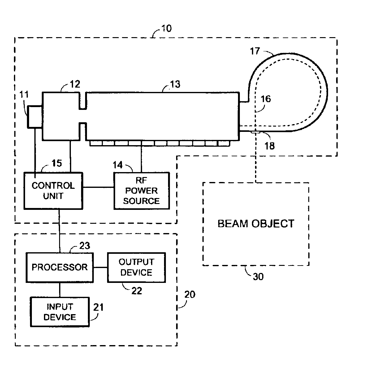
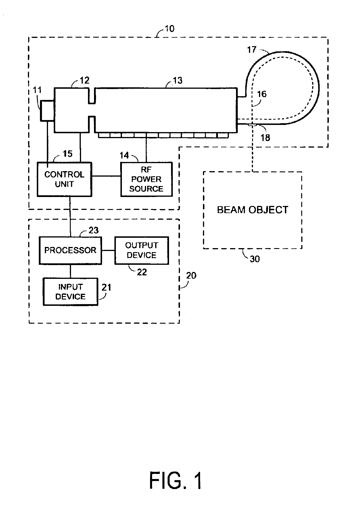
FIG. 1 illustrates an implementation according to some embodiments which includes particle accelerator 10, operator console 20 and beam object 30.

Particle accelerator 10 may be used to output particle bunches toward beam object 30 in response to commands received from operator console 20. According to some embodiments, the output particle bunches have a first energy when particle accelerator 10 is operated in a first mode and have a second energy when particle accelerator 10 is operated in a second mode.

Particle accelerator 10 includes particle gun 11 for injecting particles such as electrons into prebuncher 12. Particle gun 11 may comprise a heater, a thermionic cat...


PUM


Abstract

Some embodiments include operation of an accelerator waveguide to accelerate particles to a first energy within the waveguide, wherein a prebuncher coupled to the waveguide outputs particle bunches having a first phase, change of a phase at which particle bunches will be output from the prebuncher from the first phase to a second phase, and operation of the accelerator waveguide to accelerate particles to a second energy within the waveguide, wherein the prebuncher outputs particle bunches having the second phase. Further aspects provide change of a resonant frequency of the prebuncher from a first frequency to a second frequency. According to still further aspects, the prebuncher includes a prebuncher cavity and change of the resonant frequency comprises change of a shape of the prebuncher cavity.

Description

BACKGROUND1. FieldThe present invention relates generally to particle accelerators. More particularly, embodiments of the present invention relate to particle accelerators having multiple output energies.2. Description of the Related ArtA particle accelerator produces charged particles having particular energies. In one common application, a particle accelerator produces a radiation beam used for medical radiation therapy. The beam may be directed toward a target area of a patient in order to destroy cells within the target area.A conventional particle accelerator includes a particle source, an accelerator waveguide and a microwave power source. The particle source may comprise an electron gun that generates and transmits electrons to the waveguide. The waveguide also receives electromagnetic waves from the microwave power source, such as a magnetron or a klystron. The electrons are accelerated through the waveguide by oscillations of the electromagnetic waves within cavities of the...

Claims


Application Information

Patent Timeline
Patent Type & Authority Patents(United States)
IPC IPC(8): H05H7/14H05H7/16H05H15/00
CPCH05H15/00H05H7/16Y02E30/10
Inventor YAO, CHONG GUOWHITHAM, KENNETH
Owner SIEMENS MEDICAL SOLUTIONS USA INC
Why Eureka
Try Eureka