Multi-function input/output driver

a multi-functional input/output technology, applied in logic circuits, oscillators, pulse techniques, etc., can solve the problems of increasing circuit complexity and silicon area, little flexibility in handling signals specified by varying standards,

Inactive Publication Date: 2005-02-15
PROMISE TECHNOLOGY
View PDF4 Cites 90 Cited by
  • Summary
  • Abstract
  • Description
  • Claims
  • Application Information

AI Technical Summary

Problems solved by technology

Typically, I/O drivers provide functionality for a specific type of signaling, i.e., either single-ended or differential, and therefore offer little flexibility in handling signals specified by varying s

Method used


Image

  • Multi-function input/output driver
  • Multi-function input/output driver
  • Multi-function input/output driver

Examples


Embodiment Construction

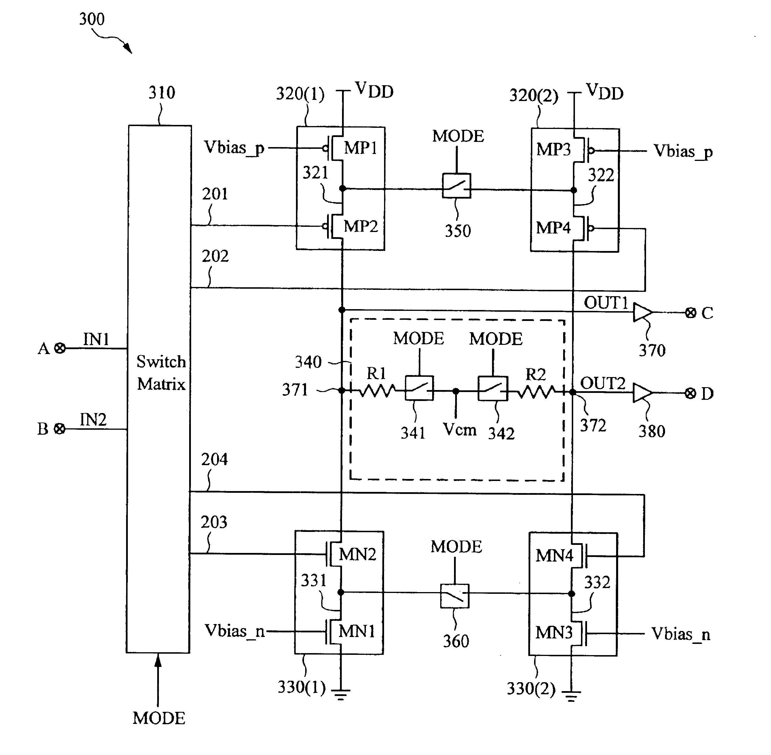
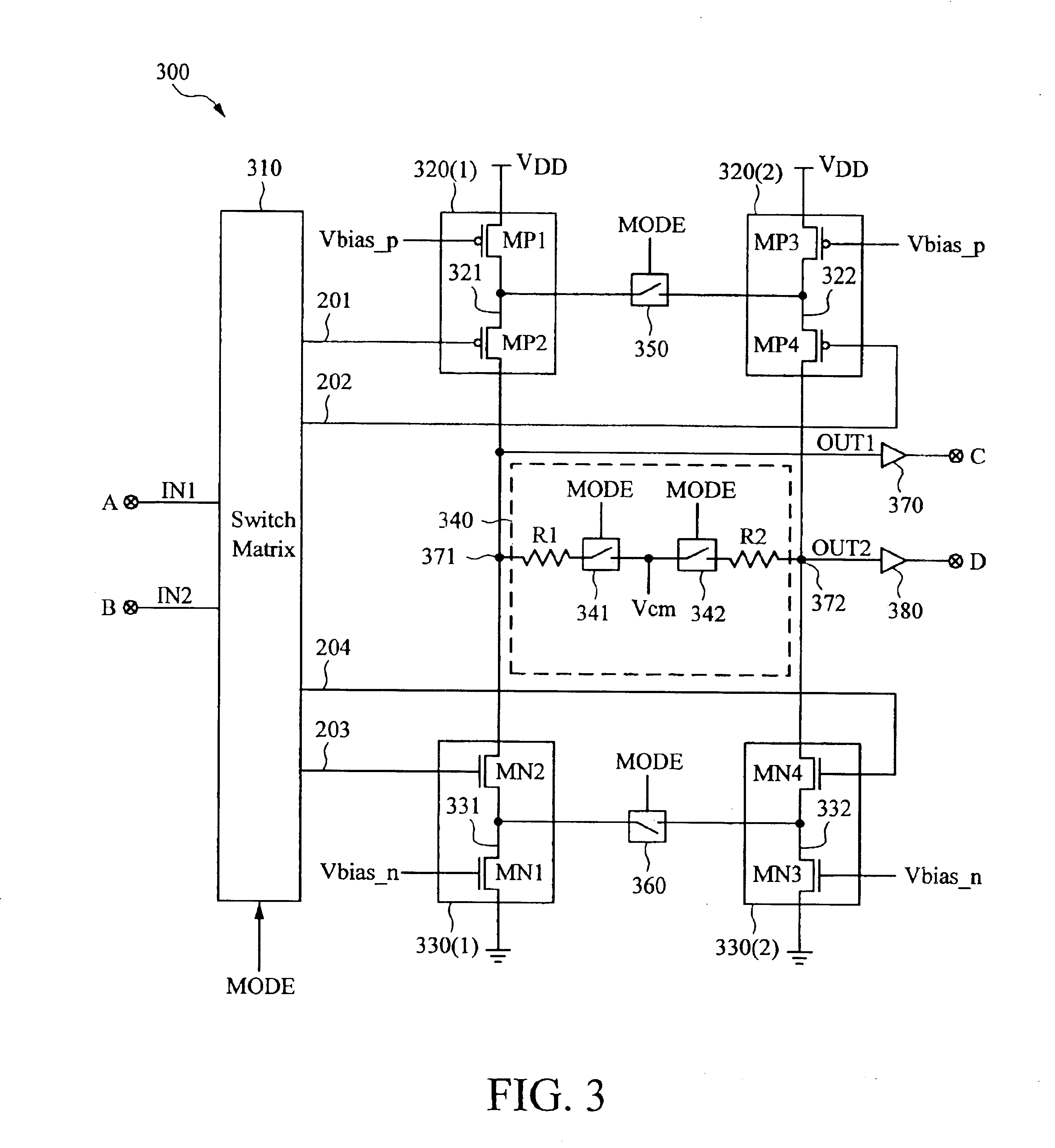
In accordance with the present invention, a high-speed I / O driver is disclosed that can process signals specified by both single-ended and differential I / O standards. The high-speed driver includes circuitry that is configurable to meet single-ended and differential I / O signal standards without the need for different drivers on each I / O pad to implement the various standards, thereby increasing flexibility while minimizing circuit complexity and silicon area.

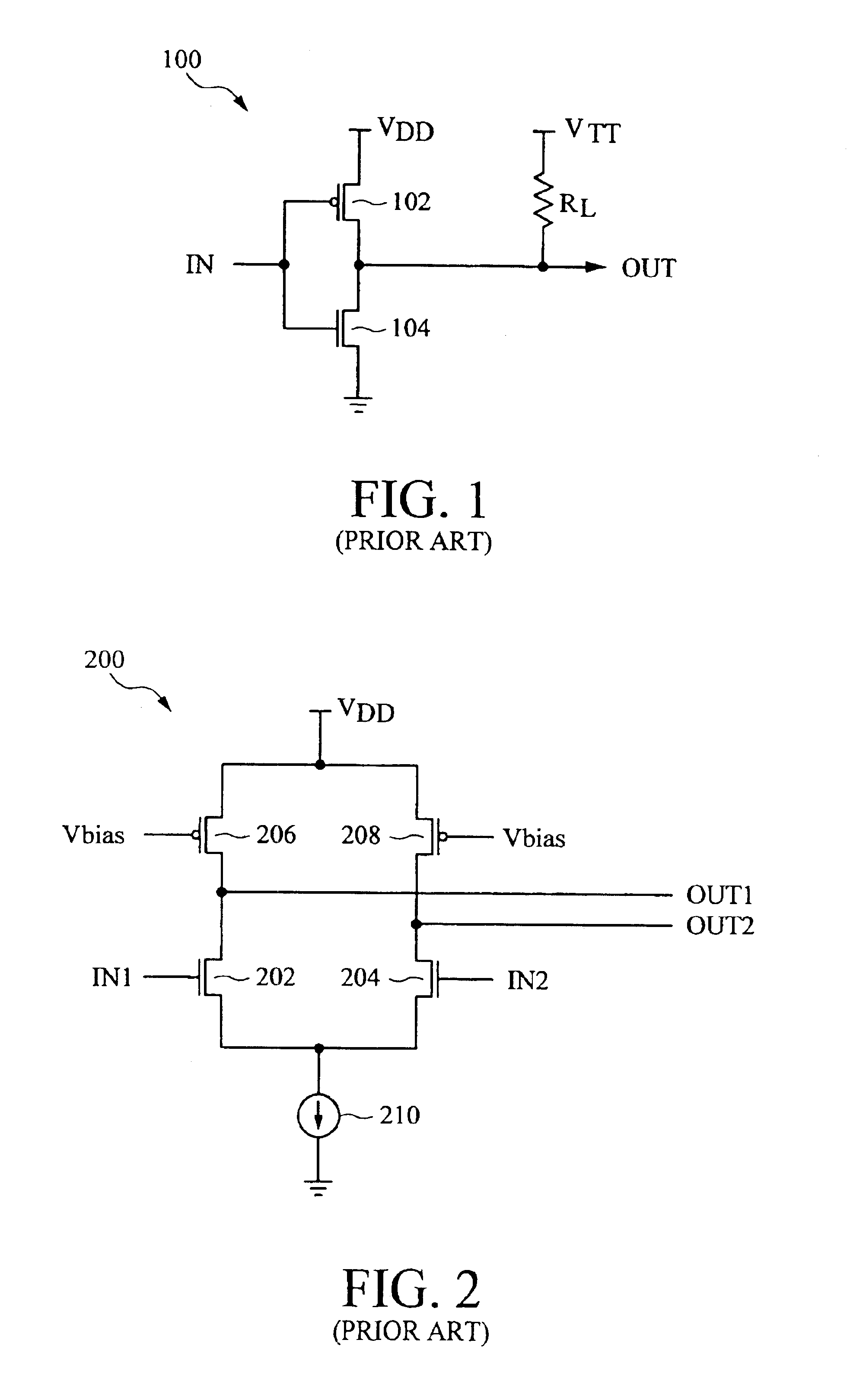
In the following description, exemplary embodiments are described in order to provide a thorough understanding of the present invention. For purposes of explanation, specific nomenclature is set forth to provide a thorough understanding of the present invention. However, it will be apparent to one skilled in the art that these specific details may not be required to practice the present invention. In other instances, well-known circuits and devices are shown in block diagram form to avoid obscuring the present invention unnecess...


PUM


Abstract

A high-speed I/O driver includes circuitry that is configurable to meet single-ended and differential I/O signal standards. For one embodiment, the driver includes four input circuits that can be configured to implement two CMOS inverters to process single-ended signals or configured to implement a differential circuit to process differential signals.

Description

FIELD OF INVENTIONThe present invention relates generally to integrated circuits and specifically to input / output (I / O) drivers for integrated circuits.DESCRIPTION OF RELATED ARTChanging system requirements are driving the need for high bandwidth input / output (I / O) interface standards support. Thus, higher performance systems, driven by faster processors and memories, are increasing the need for higher bandwidth data transfers. In response to these system changes, new I / O standards are continually emerging. For example, many modern processing systems use the High Speed Transceiver Logic (HSTL) standard for data transfers to and from memory, and use the Low Voltage Differential Signaling (LVDS) standard for backplane communications.The HSTL standard, which includes several classes, specifies the output characteristics for single-ended outputs having both series terminating loads (Class II) and parallel terminating loads (Classes (I, III, and IV). The HSTL standard does not specify de...

Claims


Application Information

Patent Timeline
IPC IPC(8): H03K19/0185
CPCH03K19/018585
Inventor NARAYAN, SRIRAM
Owner PROMISE TECHNOLOGY
Why Eureka
Try Eureka