Dual band spiral-shaped antenna

a spiral-shaped antenna and antenna technology, applied in the direction of antennas, antenna details, simultaneous aerial operations, etc., can solve the problems of small volume of state-of-the-art communication devices such as handsets, insufficient space for conventional quarter-and-half and insufficient space for conventional quarter-wave length antenna elements. , to achieve the effect of small volum

Inactive Publication Date: 2005-02-15
SKYCROSS INC
View PDF16 Cites 29 Cited by
  • Summary
  • Abstract
  • Description
  • Claims
  • Application Information

AI Technical Summary

Benefits of technology

[0015]The present invention comprises a multi-band antenna (i.e., operative or resonant in more than one frequency band). The antenna comprises conductive material having a spiral shape and a ground plane spaced apart from the conductive material. A shorting leg extends from the conductive material and is connected to a ground plane. The signal feed leg extends from the conductive material. The signal feed leg provides the signal to the antenna for transmission in the transmitting mode and provides the received signal to receiving equipment in the receiving mode. Advantageously, the antenna provides multiple resonant frequencies in a relatively small volume for use with communications devices, especially handset devices.

Problems solved by technology

Smaller packaging of state-of-the-art communications devices, such as handsets, does not provide sufficient space for the conventional quarter and half wave length antenna elements.
However, conventional loop antennas are too large for handset applications and do not provide multi-band operation.
Although small compared to a quarter or half wavelength antenna, the patch antenna has a relatively poor radiation efficiency, i.e., the resistive return losses are relatively high.

Method used


Image

  • Dual band spiral-shaped antenna
  • Dual band spiral-shaped antenna
  • Dual band spiral-shaped antenna

Examples


Embodiment Construction

s;

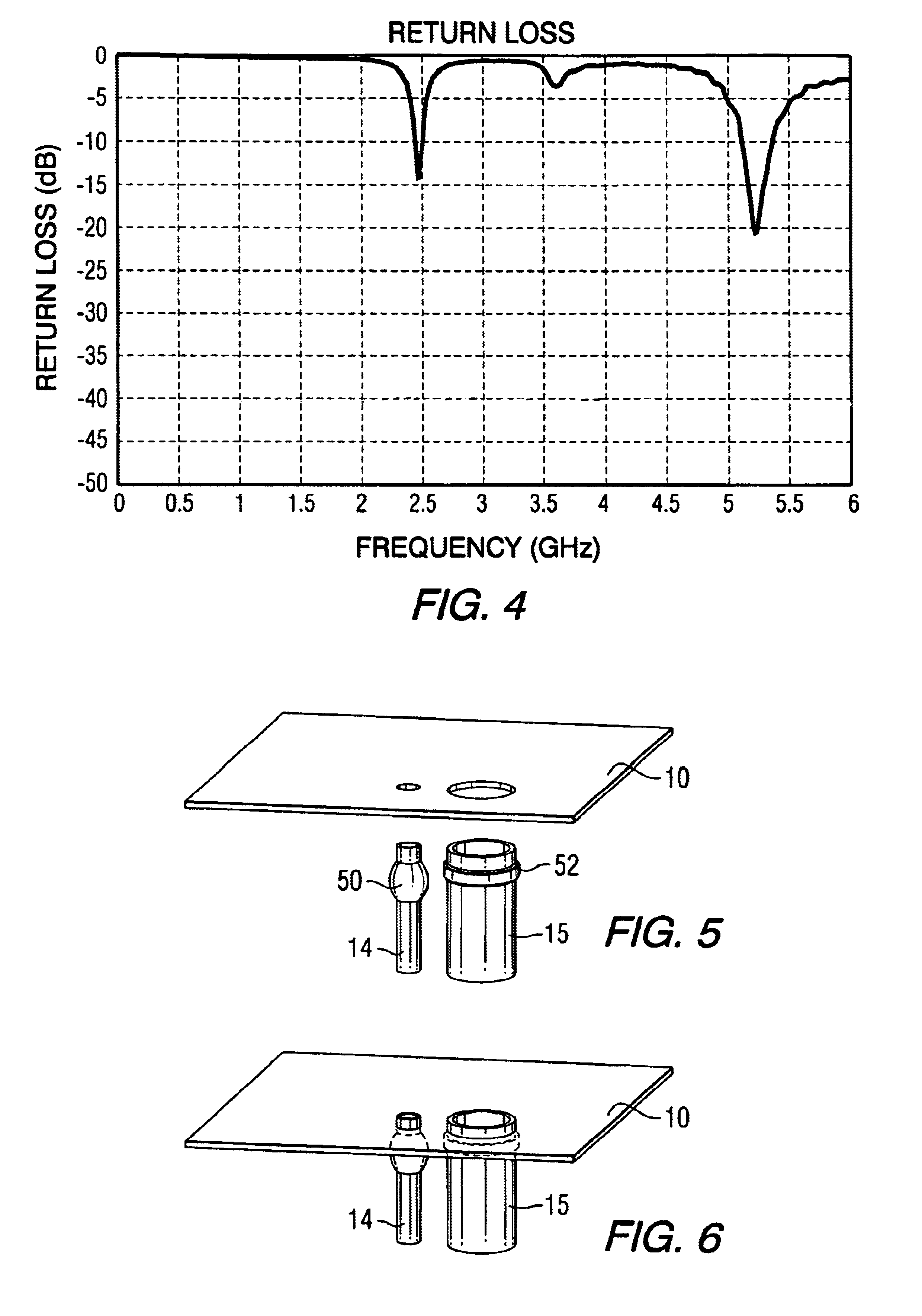
[0024]FIGS. 11 and 12 illustrate alternative assembly process for the pins of FIGS. 5 through 8;

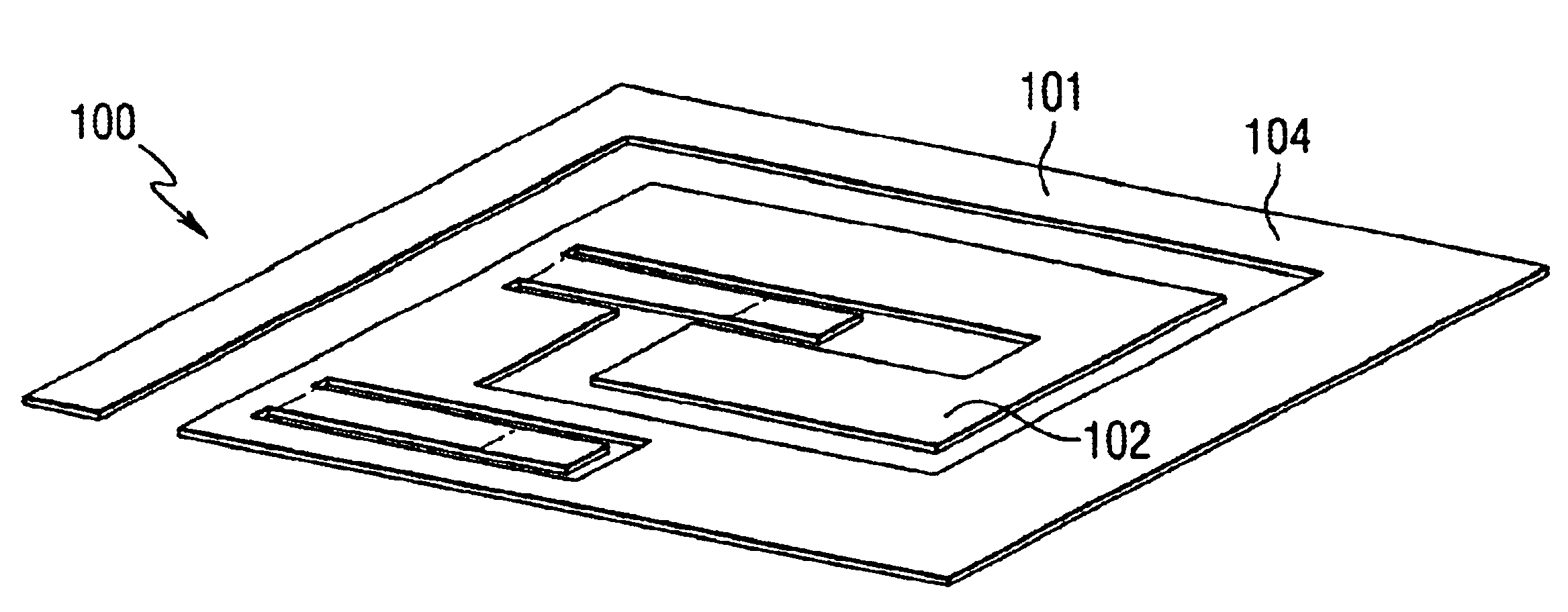
[0025]FIGS. 13 through 15 are perspective views of an antenna according to a second embodiment of the present invention;

[0026]FIGS. 16 and 17 illustrate the current distribution of the antenna of FIGS. 13 through 15;

[0027]FIGS. 18 through 20 are top views or alternative embodiments of the antenna of FIGS. 13 through 15;

[0028]FIG. 21 is a perspective view of the antenna of FIGS. 13 through 15 disposed over a ground plane; and

[0029]FIG. 22 is a graph illustrating the return loss of the antenna of FIGS. 13 through 15.

[0030]FIG. 23 is a communication device including an antenna constructed according to the teachings of the present invention.

DETAILED DESCRIPTION OF THE INVENTION

[0031]Before describing in detail the particular antennas in accordance with the various embodiments of the present invention, it should be observed that the present invention resides primarily in a novel combination ...


PUM


Abstract

A planar antenna comprising a spiral conductive surface comprising an inner spiral segment and an outer spiral segment. A shorting leg for connection to a ground plane and a feed leg responsive to the antenna signal (in the transmit and the receive modes) extend downwardly from the plane of the spiral segments. Performance characteristics of the antenna are responsive to the configuration and spacing of the spiral segments and the distance between the antenna and the ground plane.

Description

[0002]This patent application claims the benefit of the Provisional Patent Application No. 60 / 338,527 filed on Nov. 2, 2001, and the Provisional Patent Application No. 60 / 354,828 filed on Feb. 6, 2002.FIELD OF THE INVENTION[0003]The present invention is directed generally to antennas for receiving and transmitting radio frequency signals, and more particularly to spiral-shaped antennas operative in multiple frequency bands.BACKGROUND OF THE INVENTION[0004]It is generally known that antenna performance is dependent upon the size, shape and material composition of the constituent antenna elements, as well as the relationship between certain antenna physical parameters (e.g., length for a linear antenna and diameter for a loop antenna) and the wavelength of the signal received or transmitted by the antenna. These relationships determine several antenna operational parameters, including input impedance, gain, directivity, signal polarization, operating frequency, bandwidth and radiation...

Claims


Application Information

Patent Timeline
Patent Type & Authority Patents(United States)
IPC IPC(8): H01Q9/04H01Q5/00H01Q1/36H01Q1/24H01Q5/371
CPCH01Q1/243H01Q5/371H01Q9/0421H01Q1/36
Inventor JO, YOUNG-MINKIM, YOUNG-KICAIMI, FRANK M.FARRAR, JOHN CHARLESNELSON, MARK D.GREER, KERRY LANE
Owner SKYCROSS INC
Why Eureka
Try Eureka