Digital signal sub-band separating/combining apparatus achieving band-separation and band-combining filtering processing with reduced amount of group delay

a technology of filtering processing and digital signal, applied in the field of subband separation/combining apparatus, can solve problems such as serious disadvantages in the amount of delay, and achieve the effect of reducing the amount of filter delay and more effective suppression

Inactive Publication Date: 2005-02-15
PANASONIC CORP
View PDF12 Cites 40 Cited by
  • Summary
  • Abstract
  • Description
  • Claims
  • Application Information

AI Technical Summary

Benefits of technology

The apparatus moreover provides an echo canceller apparatus in which a digital audio signal received from a remote location to be audibly reproduced by a loudspeaker is subjected to sub-band separation and then adaptive filtering of the respective sub-band signals, a digital audio signal obtained from a microphone which may be adjacent to the loudspeaker is also converted to a set of sub-band signals, the differences between these signals and the adaptively filtered sub-band signals are obtained as respective error signals and applied to update the coefficients of the adaptive filters, and are also subjected to band-combining filter processing to obtain an output digital signal that is returned to the remote location, in which the sub-band separating and sub-band combining processing are performed using low-delay sub-band separating apparatuses and a low-delay sub-band combining apparatus according to the invention. As a result, due to the reduced amounts of filter delay, more effective suppression can be achieved of a signal that is returned to the remote location as an echo.

Problems solved by technology

In many applications, such an amount of delay becomes a serious disadvantage.

Method used


Image

  • Digital signal sub-band separating/combining apparatus achieving band-separation and band-combining filtering processing with reduced amount of group delay
  • Digital signal sub-band separating/combining apparatus achieving band-separation and band-combining filtering processing with reduced amount of group delay
  • Digital signal sub-band separating/combining apparatus achieving band-separation and band-combining filtering processing with reduced amount of group delay

Examples


first embodiment

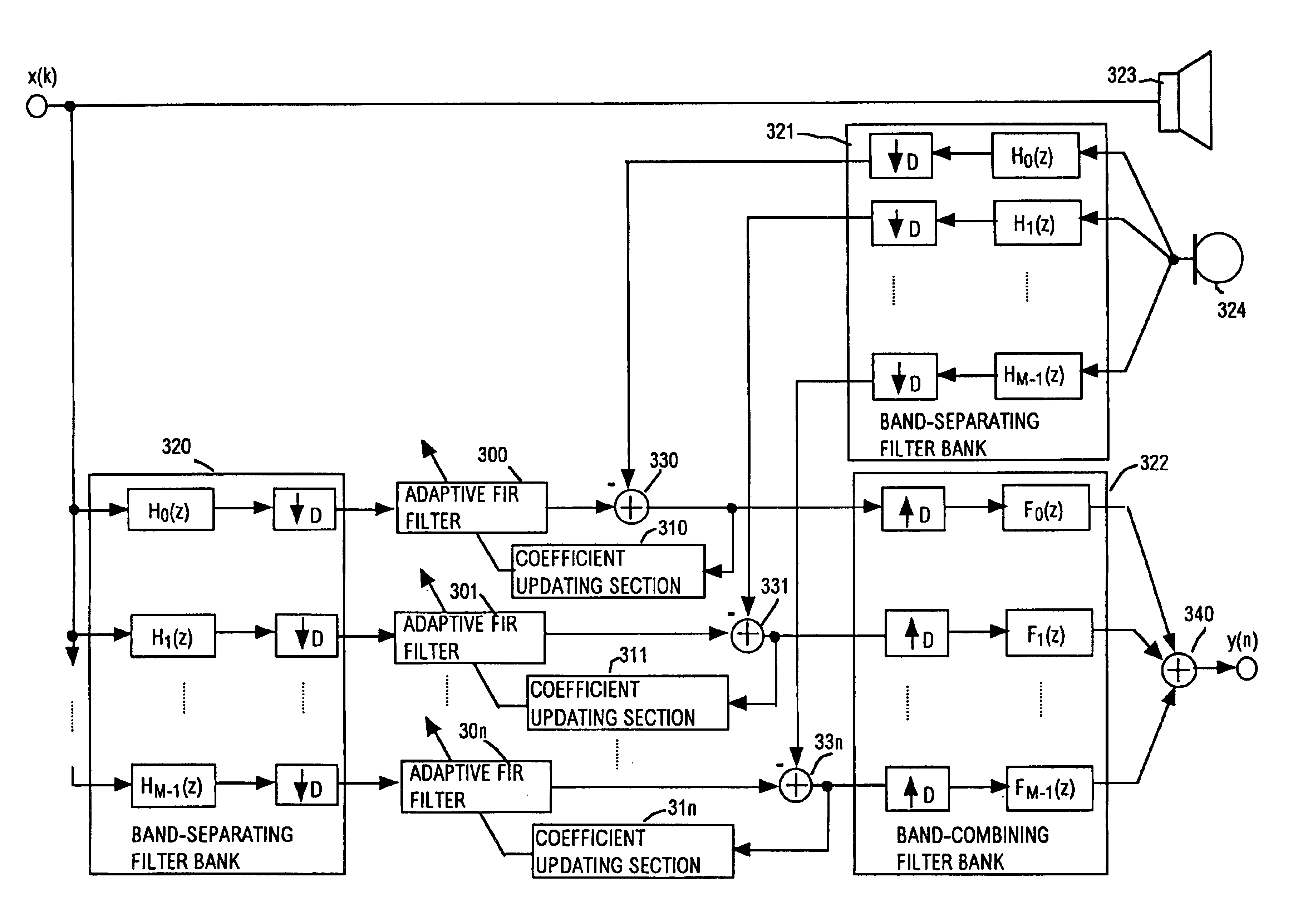
FIG. 1 is a general system block diagram of a first embodiment of the invention, which is a combination of a sub-band separating apparatus and a sub-band combining apparatus, for use with a processing (or transmitting / receiving) system. In FIG. 1, a band-separating filter bank 1 performs filtering of respective frequency bands of an input PCM digital signal x(n), then decimation is applied, using a decimation factor of D. The band-separating filter bank 1 is formed of a set of band-separating filters 010˜01n and a corresponding set of down-samplers 020˜02n, each of which applies decimation by a fixed factor D (i.e., selecting one in every D successive samples) to the output sub-band signal from the corresponding one of the band-separating filters 010˜01n. After the resultant decimated sub-band signals have been subjected to predetermined processing in a processing section 3, they are inputted to a band-combining filter bank 2, which effects interpolation of the signals, i.e., by ins...

second embodiment

FIG. 4 shows a second embodiment of the invention, which is a PCM digital audio signal compression encoding / decoding apparatus. It should be understood that the invention could of course be applied to various other types of digital signal encoding apparatus. In FIG. 4, an encoder 101 receives as input a PCM digital audio signal, performs sub-band separating processing, and uses human psycho-acoustic response characteristics etc., to perform compression encoding processing. The encoder 101 is formed of a band-separating filter bank 102, psycho-acoustic model section 103, quantization / encoding section 104 and frame forming section 105.

The band-separating filter bank 102 is formed as described hereinabove for the band-separating filter bank 1 of the first embodiment, for the case in which this is a cosine modulation filter bank in which the band-separating filters are configured in accordance with equation (7) above, with a decimation factor D that is identical to the separation factor...

third embodiment

FIG. 5 shows the system configuration of a third embodiment of the invention. This is a wireless microphone system which uses sub-band compression encoding / decoding processing having a low amount of delay, implemented as described above for the second embodiment. As a result with this system, by comparison with the prior art, there is a reduced amount of delay between the time at which a sound is received by a microphone of the system and the time at which a corresponding amplified sound is emitted from a loudspeaker.

In FIG. a transmitter 200 applies A-D conversion to convert an audio signal from a microphone into a PCM digital audio signal, then applies compression encoding processing as described hereinabove for the second embodiment of the invention, to obtain a compressed bit stream. The bit stream is then subjected to encoding conversion to reduce the effects of errors which may arise when the bit stream traverses a transmission path, and the resultant signal is then applied in...


PUM


Abstract

An apparatus having a band-separating filter bank for separating a digital signal into a plurality of sub-band signals, to be processed or transmitted, and a band-combining filter bank for subsequently combining the resultant sub-band signals into a single digital signal, wherein each of the band-separating filter bank and band-combining filter bank incorporates a FIR low pass filter having an asymmetric impulse response, as the prototype filter of the filter bank. A significant reduction can thereby be achieved in the amount of overall group delay that results from the processing performed by these filter banks.

Description

BACKGROUND OF THE INVENTION1. Field of the InventionThe invention relates to a sub-band separating / combining apparatus having a band-separating filter bank for converting a digital signal to a plurality of sub-band signals and a band-combining filter bank which receives the sub-band signals after processing or transmission thereof, for combining these to recover the original digital signal or a processed version of that signal2. Description of the Related ArtThere are various applications in which a digital signal is supplied to a set of filters of a band-separating filter bank (sometimes referred to as an analyzing filter bank) to be spectrally divided into a plurality of sub-band signals, i.e., respectively corresponding to different frequency bands, with the sample rate of each of the sub-band signals then being reduced by decimation (i.e., down-sampling). Processing or transmission of the resultant low-bandwidth sub-band signals can then be efficiently performed. After processin...

Claims


Application Information

Patent Timeline
Patent Type & Authority Patents(United States)
IPC IPC(8): H03H17/02
CPCH03H17/0266H03H2021/0041
Inventor TANIGUCHI, SHOHEIITO, MASAYUKIBANBA, YUTAKA
Owner PANASONIC CORP
Why Eureka
Try Eureka