Signal processing method and apparatus and disk device using the method and apparatus

a signal processing and signal technology, applied in the field of signal processing techniques and disk devices, can solve the problems of data sync signal not being successfully detected, data for one sector cannot be correctly reproduced, and the error rate of the whole apparatus is considerably deteriorated, so as to reduce the error in data sync signal detection

Inactive Publication Date: 2005-02-15
HITACHI GLOBAL STORAGE TECH JAPAN LTD
View PDF18 Cites 7 Cited by
  • Summary
  • Abstract
  • Description
  • Claims
  • Application Information

AI Technical Summary

Benefits of technology

An object of the present invention is to provide a signal processing...

Problems solved by technology

The data sync signal cannot be successfully detected, therefore, even when a code string is divided into a bit string of odd numbered bits and a bit string of even numbered bits.
(If a permanent bit drop-off in the data sync signal unit occurs due to a defect of the medium, etc. data for one sector cannot be correctly reproduced.)
As described above, an erroneous detection...

Method used


Image

  • Signal processing method and apparatus and disk device using the method and apparatus
  • Signal processing method and apparatus and disk device using the method and apparatus
  • Signal processing method and apparatus and disk device using the method and apparatus

Examples


Embodiment Construction

Embodiments of the present invention will be described in detail below with reference to the accompanying drawings.

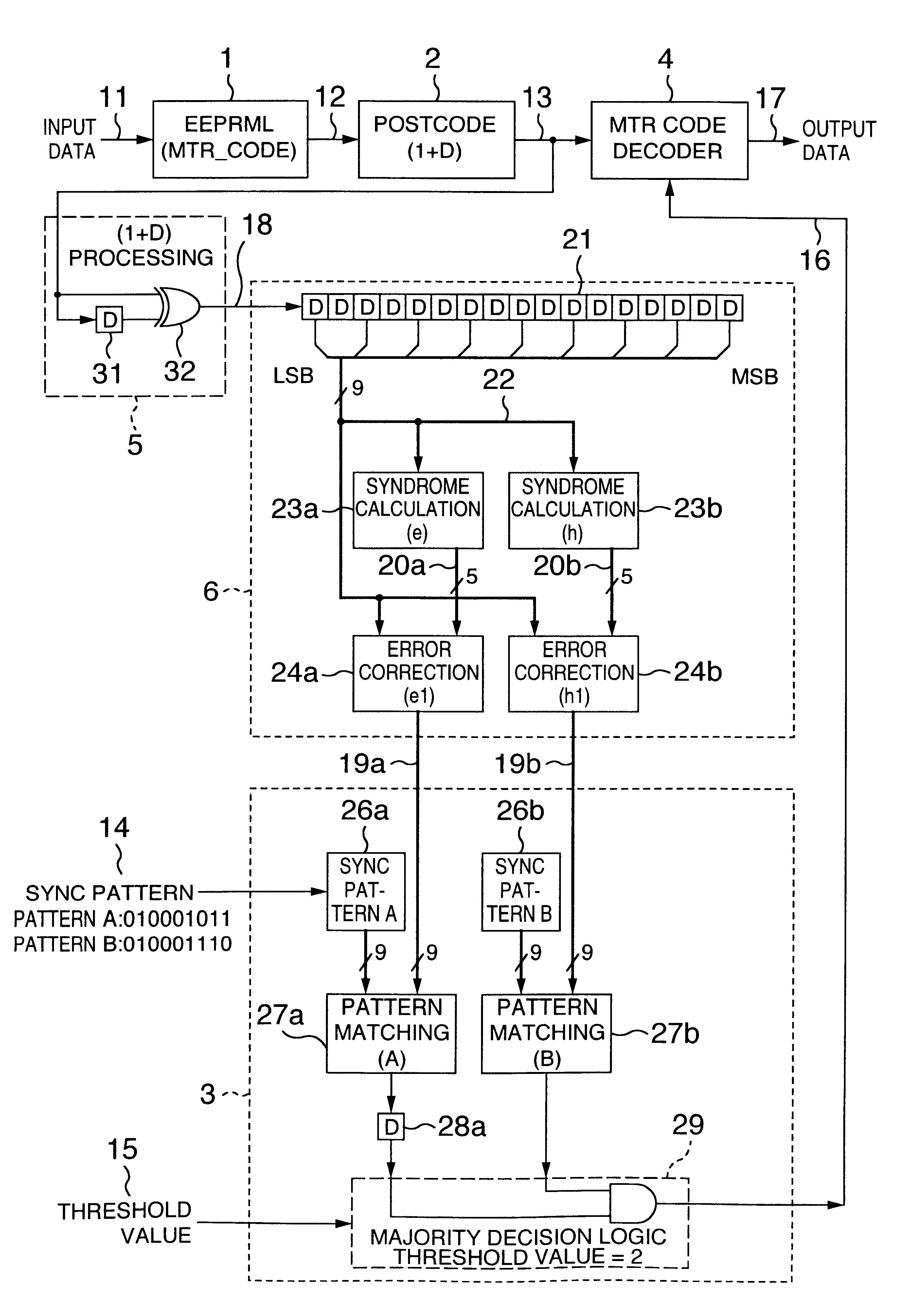
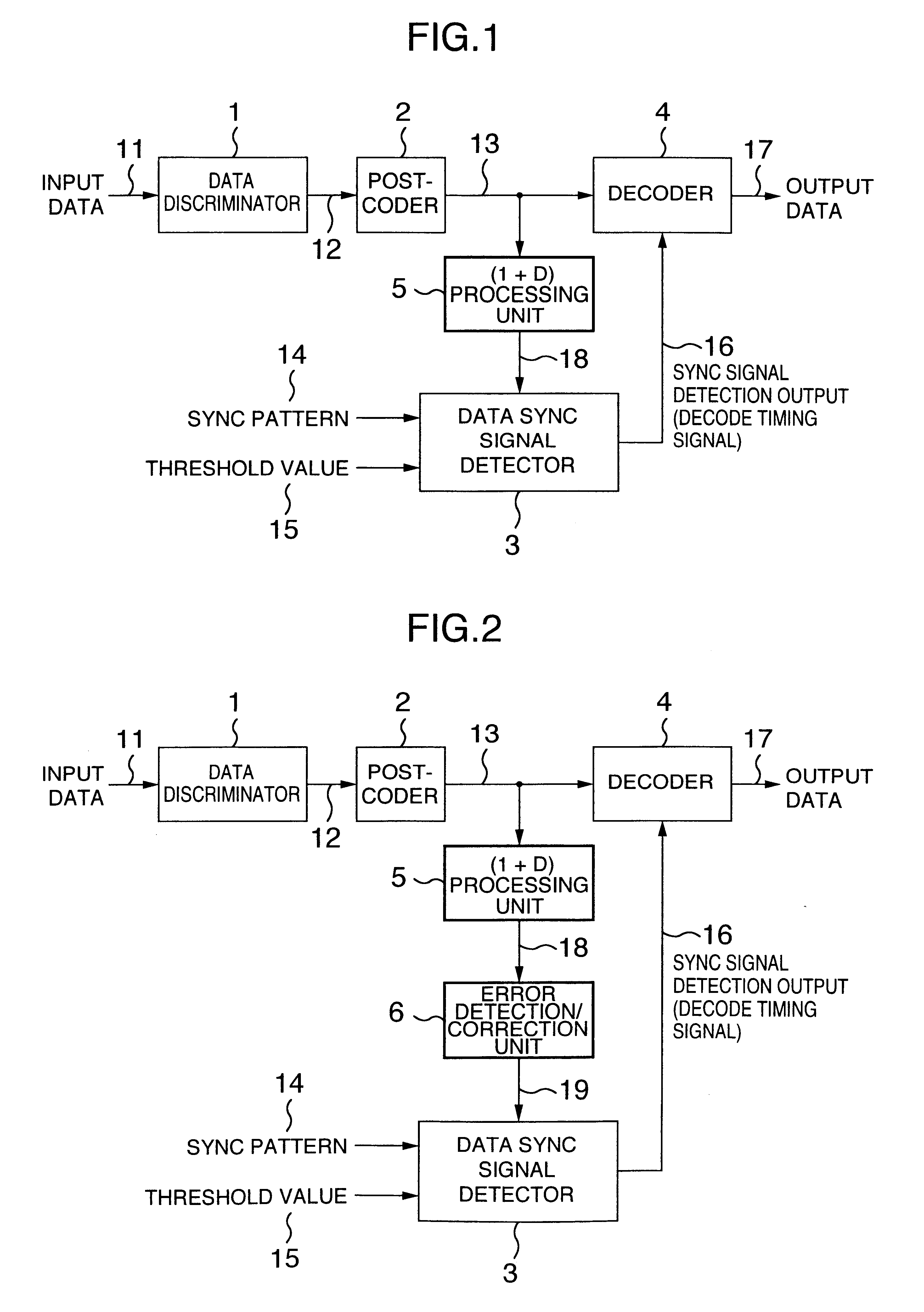
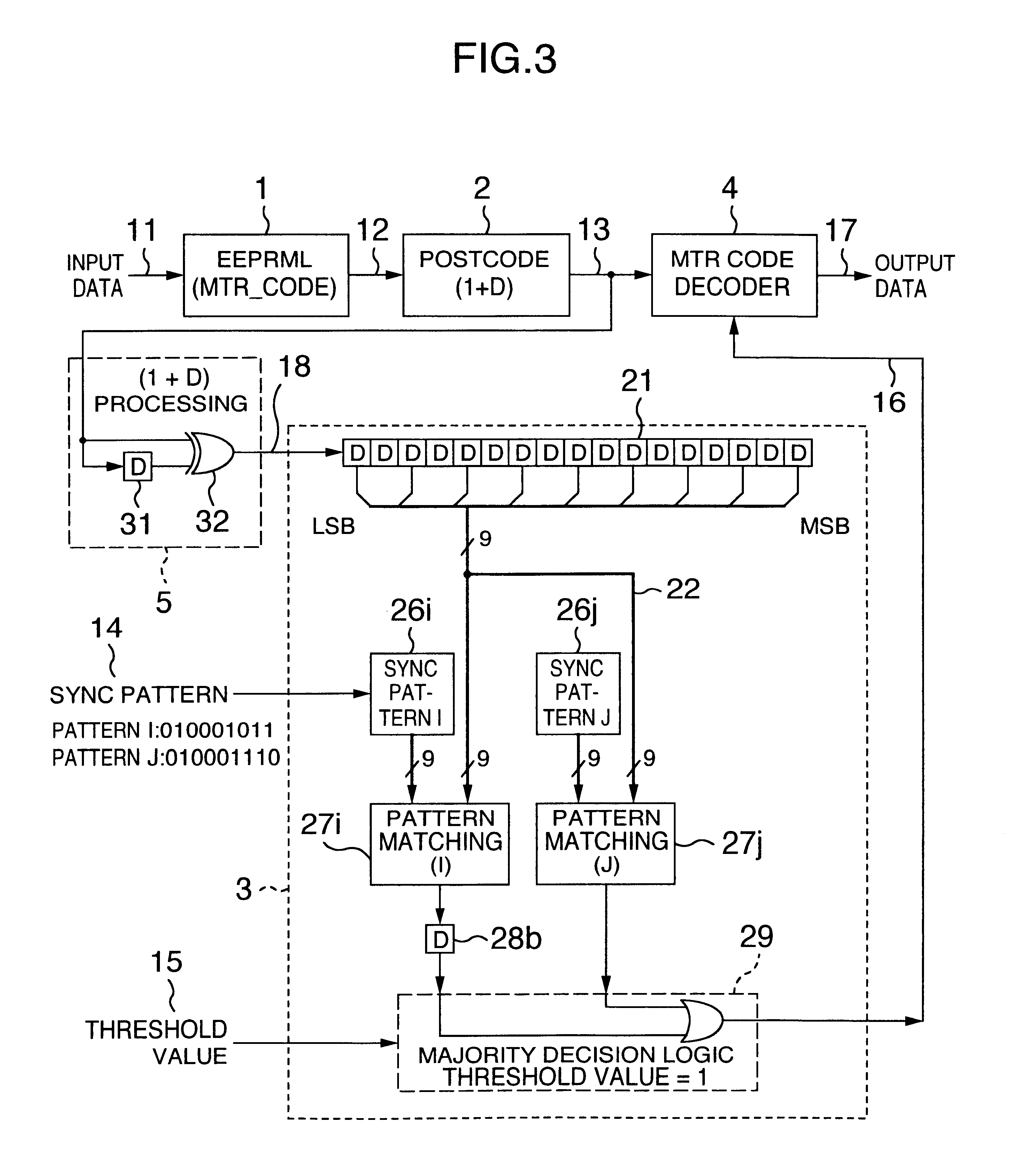
FIG. 1 is a block diagram showing a signal processing apparatus according to an embodiment of the invention.

In FIG. 1, input data 11 are input to a data discriminator 1, and a data discrimination output 12 providing a code bit output discriminated by the data discriminator 1 is input to a post-coder 2 for performing a predetermined post-code processing. Further, a post-coder output 13 is input to a decoder 4 and a (1+D) processing unit 5. A (1+D) processing output 18 is input to a data sync signal detector 3, and is compared with or matched against a sync pattern 14 by a predetermined method. In the case where the number of pattern coincidences is not less than a threshold value 15, a sync signal detection output 16 is output. The sync signal detection output 16 is applied to the decoder 4 and gives a decode timing of the code string of the post-code output 13. As a res...


PUM


Abstract

A signal processing circuit having a data sync signal detector and a disk device. Input data read from a magnetic disk is input to a data discriminator. A data discrimination output constituting a code bit output discriminated by the data discriminator is input to a post-coder the output of which is input to a decoder and a (1+D) processing unit. The processed output of the processing unit is input to an error detection/correction unit and separated into bit strings of odd numbered bits and even numbered bits, divided into groups. An error detection/correction output is input to a data sync signal detector, and matched against a sync pattern. When the number of coincident groups is greater than a threshold value, a sync signal is output and upon detection causes the decoder to demodulate the data.

Description

BACKGROUND OF THE INVENTIONThe present invention relates to a signal processing technique, and a disk device such as a magnetic disk drive or a magneto-optic disk device, or more in particular to a data sync signal detection technique and a disk device using a data sync signal detection technique with an improved data sync signal detection rate in which the data sync signal can be detected even in the presence of a data discrimination error in the data sync signal field of the data read from the disk device and discriminated.FIG. 20 shows an example of the recording format for a magnetic disk drive. The data includes an ID field and a DATA field for each sector providing a unit storage area. The ID field and the DATA field each include a PLO (Phase Locked Oscillator) SYNC field 91 for pull-in of a PLL (phase locked loop), a data sync signal 92 for detecting the starting position of an ID (address information) or data for producing a demodulation timing signal of a modulated code, an...

Claims


Application Information

Patent Timeline
IPC IPC(8): G11B27/30G11B20/10G11B20/12G11B20/18H04L7/04
CPCG11B20/10009G11B20/10055H04L7/042G11B27/3027G11B20/1833G11B20/1217G11B2220/20
Inventor WATANABE, YOSHIJUKONDO, MASAHARU
Owner HITACHI GLOBAL STORAGE TECH JAPAN LTD
Why Eureka
Try Eureka