Biological signal detection apparatus Holter electrocardiograph and communication system of biological signals

Inactive Publication Date: 2005-02-15
NIHON KOHDEN CORP
View PDF13 Cites 217 Cited by
  • Summary
  • Abstract
  • Description
  • Claims
  • Application Information

AI Technical Summary

Benefits of technology

It is therefore an object of the invention to provide a biological signal detection apparatus that can construct a medical telemetry system that can eliminate inconvenience or discomfort when th

Problems solved by technology

However, in the biological signal measuring apparatus according to the proposition, if the transmission section having the three electrode parts inputs the biological signal detected by each electrode part and transmits the signal to the outside and is applied as a Holter electrocardiograph, the method of the electrode positioning for providing electrocardiogram data, namely, the position leading electrode-to-electrode potential does not match the position of the electrode that can be led properly and efficiently as a Holter electrocardiograph, thus simple and prompt electrocardiogram data cannot be provided.
Thus, for example, improvement or prevention means for occurrence of inconvenience or discomfort when the electrodes are attached to the patient or occurrence of a malfunc

Method used


Image

  • Biological signal detection apparatus Holter electrocardiograph and communication system of biological signals
  • Biological signal detection apparatus Holter electrocardiograph and communication system of biological signals
  • Biological signal detection apparatus Holter electrocardiograph and communication system of biological signals

Examples


Example

First embodiment

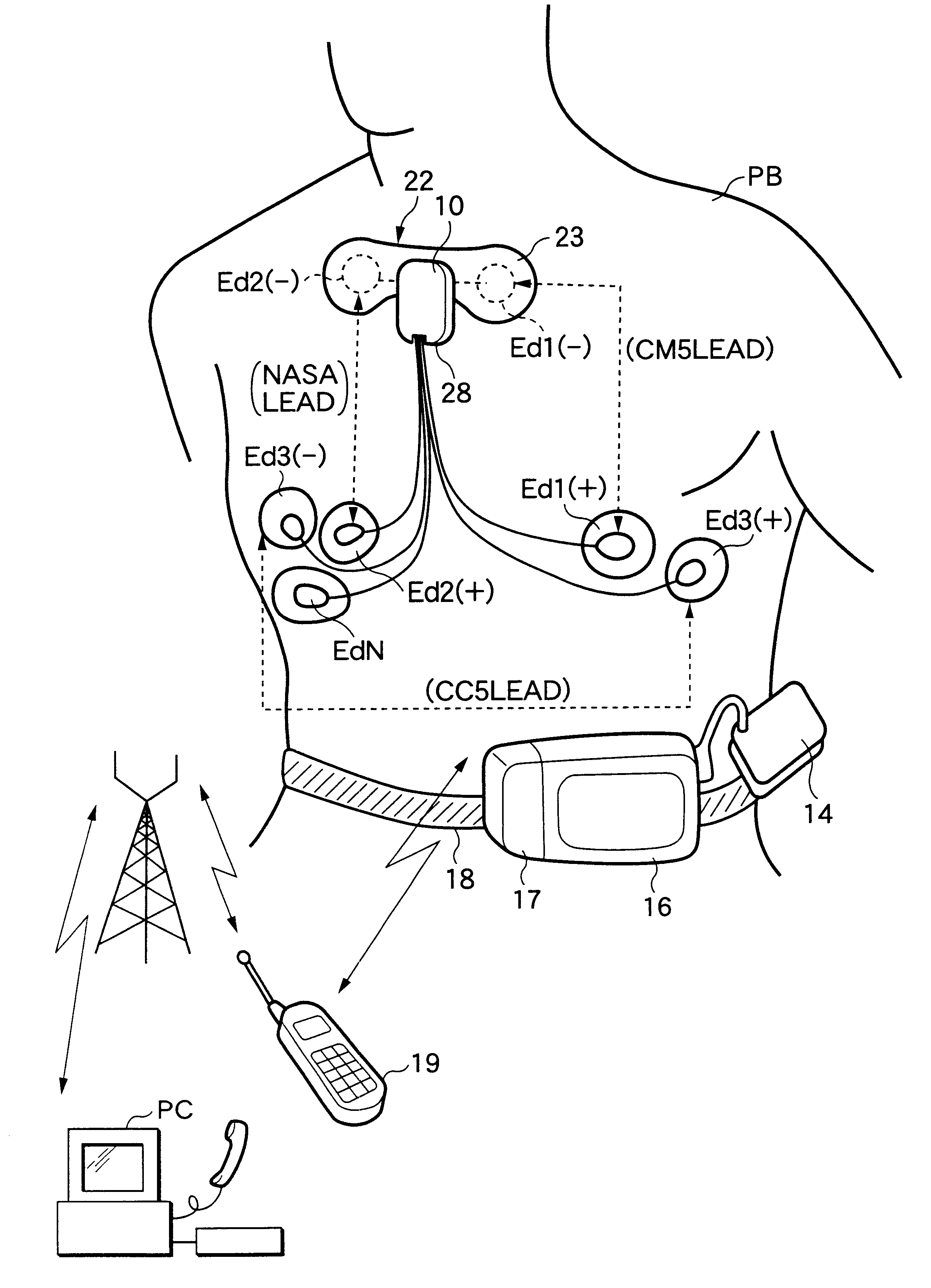
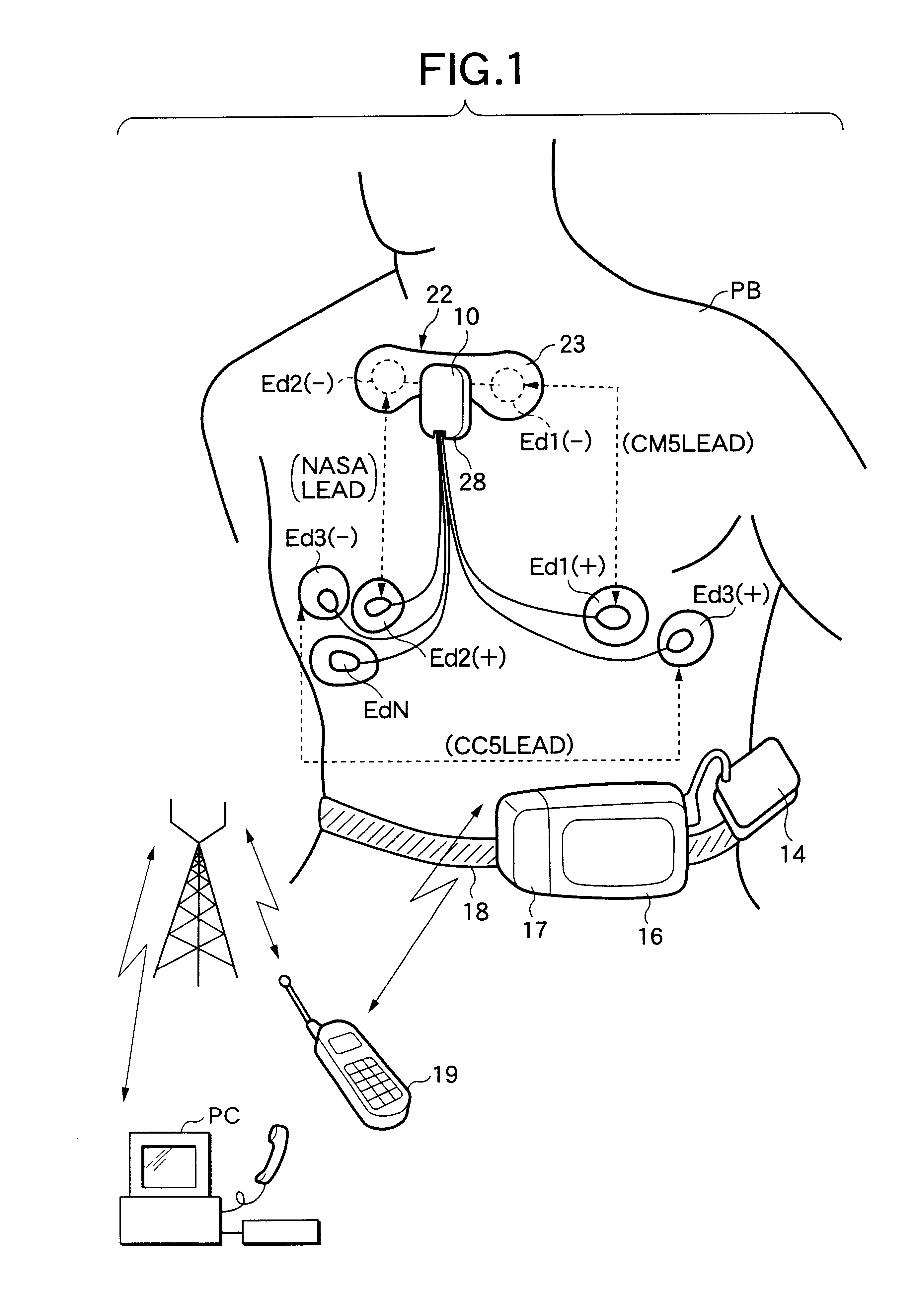
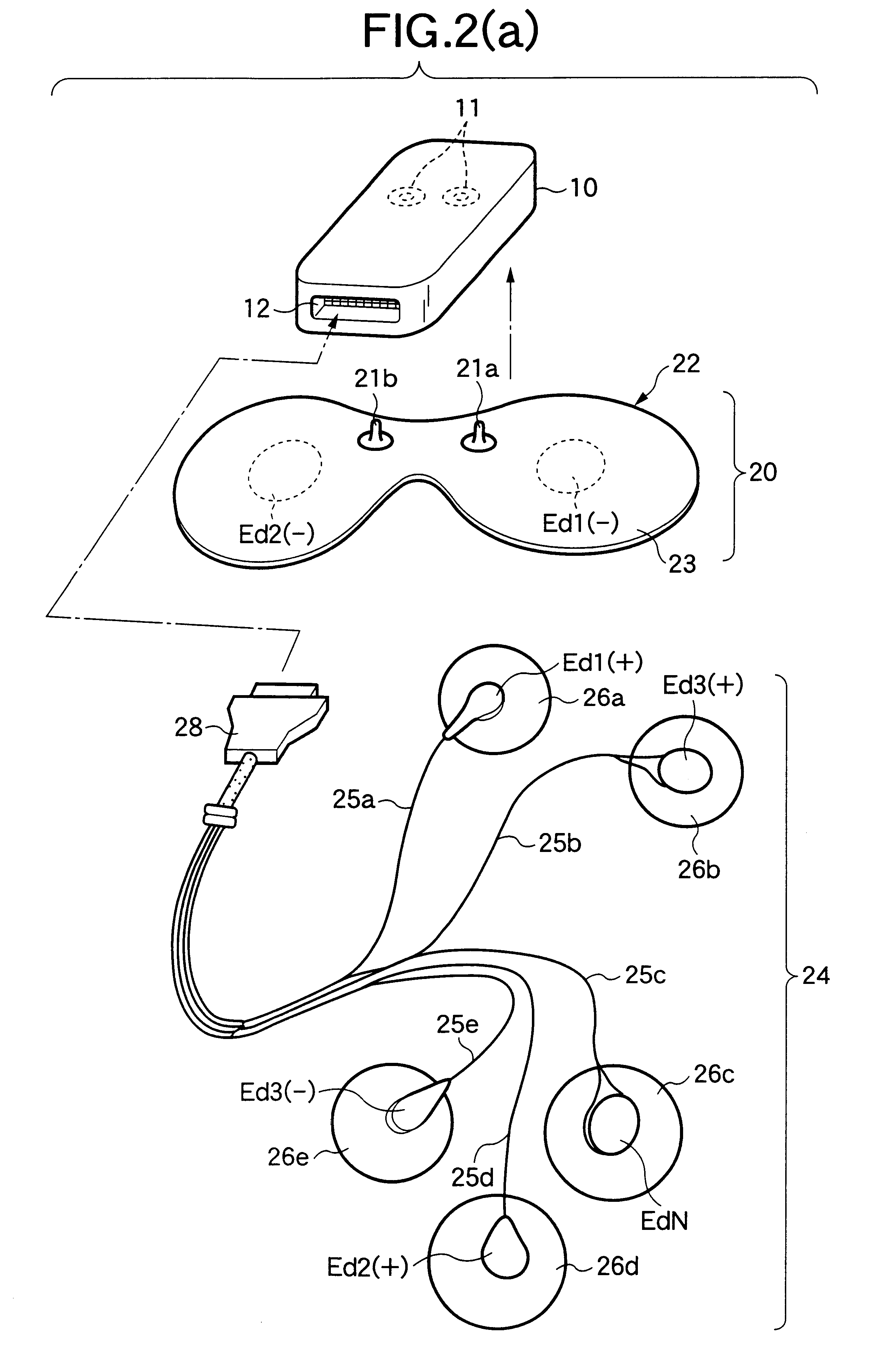
FIG. 3(a) shows an embodiment of a transmitter of a biological signal detection apparatus for detecting a biological signal according to the invention. That is, the embodiment is applied to the Holter electrocardiograph shown in FIG. 1, and the circuit configuration of a transmitter 10 of biological signal detection apparatus with a receiver 14 and a recorder 16 attached to the body of a patient PB for use is shown. Components identical with those previously described with reference to FIGS. 1 and 2 (a) and (b) are denoted by the same reference numerals in FIG. 3(a) and will not be discussed again in detail.

(1) Configuration of Transmitter as Biological Signal Detection Apparatus

The transmitter 10 as the biological signal detection apparatus shown in FIG. 3(a) is connected to a first electrode group 20 via first connection section 11 and is connected to a second electrode group 24 via a second connection section 12. The transmitter 10 comprises CM5 lead differential ...

Example

Second embodiment

FIG. 10 shows another embodiment of transmitter of biological signal detection apparatus for detecting a biological signal according to the invention. That is, in the embodiment, a data storage section and a transmitting and receiving section are contained in the transmitter of the biological signal detection apparatus in the first embodiment to form a transmitter-receiver 10A, and as a communication system, the transmitter-receiver 10A is communicatably connected to a biological signal input apparatus PC implemented as a remotely located personal computer, etc., directly or via a relay transmitter-receiver 19 of a portable telephone, etc., using a wide area network, whereby electrocardiogram data recorded in the data storage section is input to the biological signal input apparatus PC. Of course, as shown in FIG. 10, the transmitter-receiver 10A is communicatably connected to the biological signal input apparatus PC via a receiver 160 to input electrocardiogram dat...


PUM


Abstract

A communication system has a Holter electrocardiograph having a biological signal detection apparatus having a transmitter 10 for processing and telemetering signals detected by a plurality of electrodes supported on supports for detecting biological signals, a receiver 14 for receiving the signal telemetered from the transmitter, demodulating the received signal, and outputting the demodulated signal to a biological signal input section of required record means, and a recorder 16 having record means for recording the demodulated signal by the receiver. The recorder of the Holter electrocardiograph has transmitting and receiving means 17 for telemetering the signal stored in the record means, receiving an external transmission signal, and telemetering some or all of the signals stored in the record means as instructed by the external transmission signal. A biological signal input apparatus PC having transmitting and receiving means for inputting signals and transmitting and receiving communication information to and from the transmitting and receiving means of the recorder of the Holter electrocardiograph through a relay transmitter-receiver 19 and a wide area network.

Description

BACKGROUND OF INVENTION1. Field of InventionThis invention relates to a biological signal detection apparatus and in particular to a biological signal detection apparatus applicable to a medical telemetry system wherein a biological signal detected by an electrode attached to the living tissue surface of a patient can be appropriately processed and the provided signal can be telemetered by a transmitter and can be received at a remotely located monitor for monitoring the disease condition of the patient, and a Holter electrocardiograph incorporating the biological signal detection apparatus.Further, this invention relates to a communication system of detection data, etc., provided by detecting biological signals and in particular to a communication system for transmitting and receiving biological signals detected by a Holter electrocardiograph.2. Related ArtTo care for a seriously ill patient directly linked to his or her life as in an ICU (intensive care unit) or a CCU (coronary ca...

Claims


Application Information

Patent Timeline
IPC IPC(8): A61B5/0408A61B5/0402A61B5/0404A61B5/00A61B5/0432A61B5/332
CPCA61B5/0006A61B5/0404A61B5/04085A61B5/04325A61B5/0424A61B5/0008Y10S128/903A61B2560/0412A61B2560/045A61B2560/0475A61B5/332A61B5/276A61B5/282A61B5/335
Inventor MATSUMURA, FUMIYUKISEKIGUCHI, TETSUSHI
Owner NIHON KOHDEN CORP
Why Eureka
Try Eureka