Modular bridge structure construction and repair system

Inactive Publication Date: 2005-02-22
GROSSMAN STANLEY J
View PDF20 Cites 66 Cited by
  • Summary
  • Abstract
  • Description
  • Claims
  • Application Information

AI Technical Summary

Benefits of technology

The present invention provides a modular bridge structure which may be used in the construction of new bridges and also used in the repair of existing bridges. The invention utilizes modular composite structural members which may be placed on new or existing girders to provide a fast and efficient construction or repair process. The invention may b

Problems solved by technology

Large structures, such as bridges are well known and are obviously time-consuming to build or widen and even more time-consuming to rehabilitate.
Certain construction restraints, such as those in which a bridge structure is being repaired or otherwise refurbished or rehabilitated, make many prior art methods of construction more expensive and result in associated problems, such as traffic delays.
In high density traffic areas, this creates considerable traffic tie-up problems, which

Method used


Image

  • Modular bridge structure construction and repair system
  • Modular bridge structure construction and repair system
  • Modular bridge structure construction and repair system

Examples


first embodiment

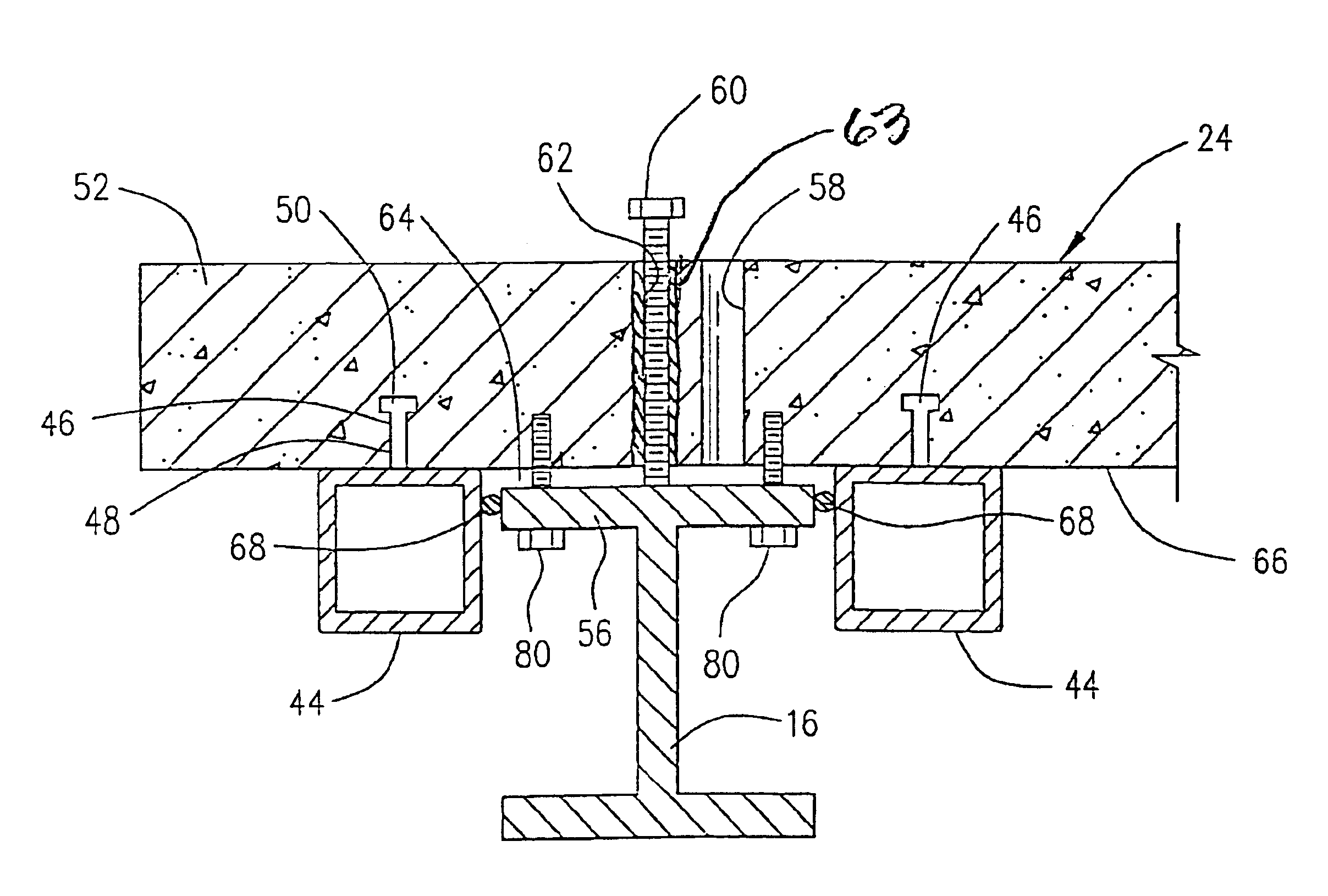
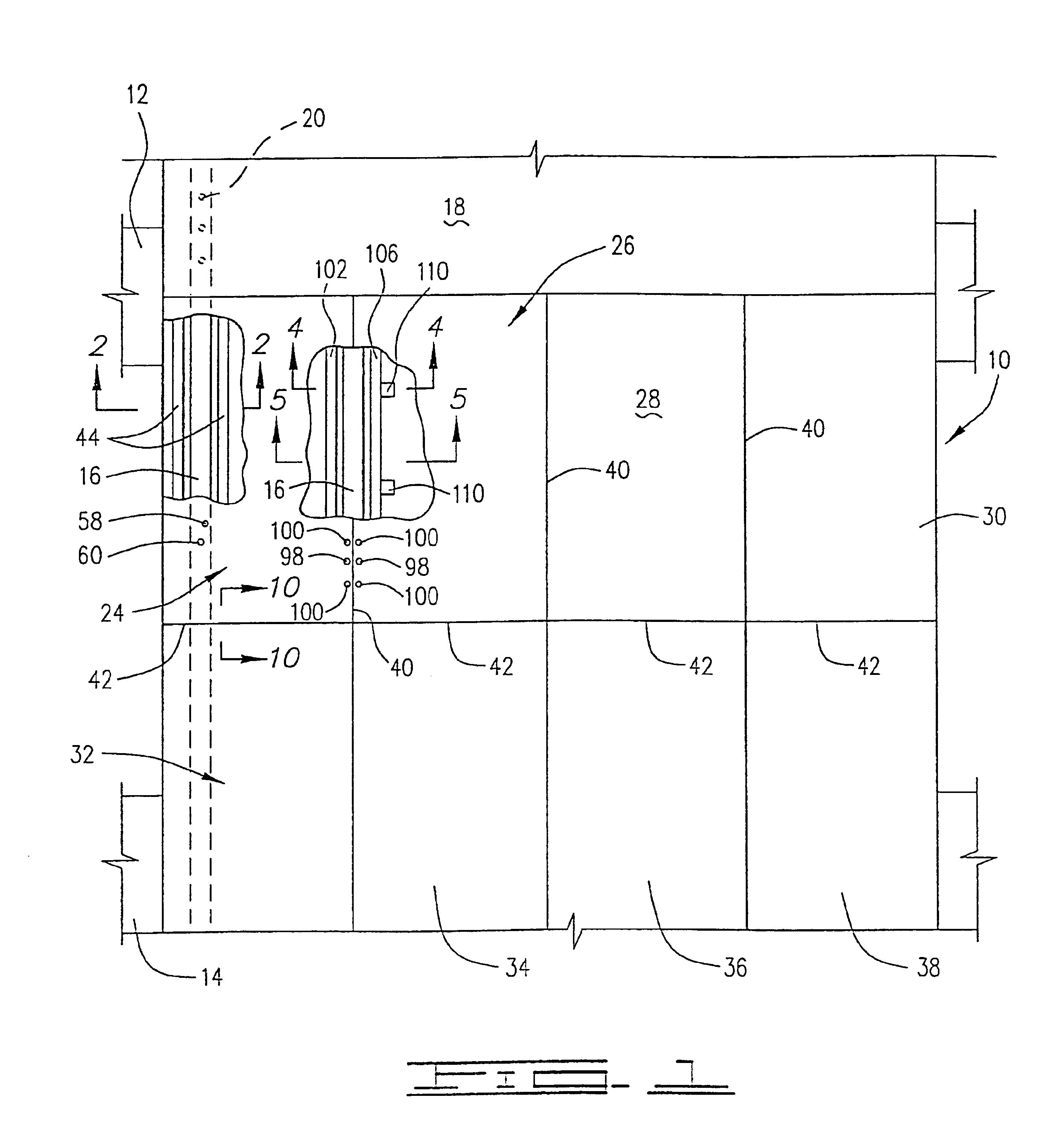
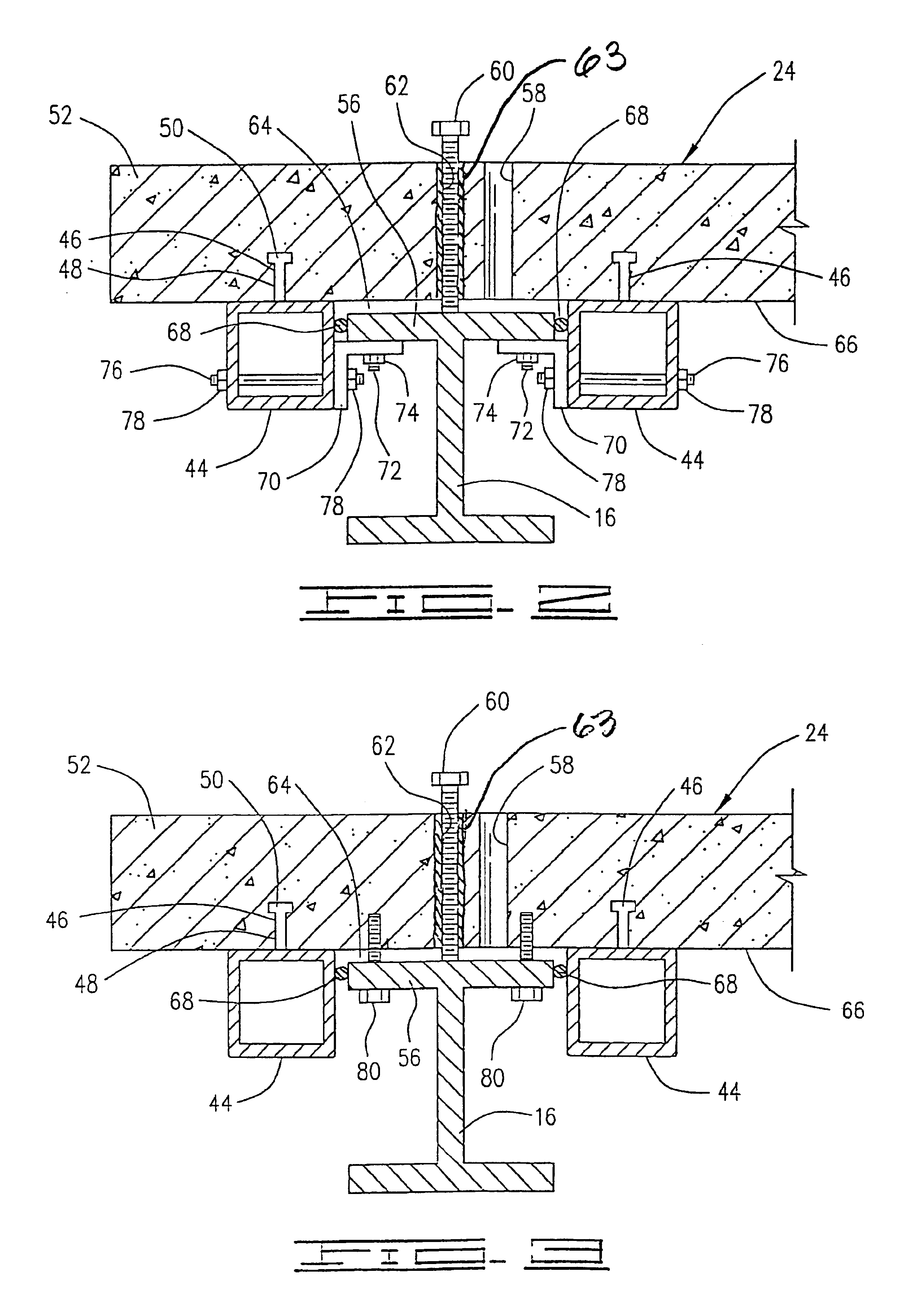
The first embodiment is shown in FIGS. 4 and 5 and is generally designated by the numeral 90. As will be further discussed herein, FIG. 4 shows the installation of modules 24 and 26 and further illustrates precompression assembly thereof. A shear connection between modules 24 and 26 and girders 16 is also shown. FIG. 5 shows additional shear connections at different locations longitudinally along girders 16 at which precompression is not applied. In other words, the precompression assembly components are not required for every shear connection.

Referring now in detail to FIG. 4, modules 24 and 26 have facing longitudinally extending sides 92 and 94 respectively. When sides 92 and 94 are positioned over girder 16 by using leveling bolts 98, sides 92 and 94 which form joint 40 are coated with a quantity of an epoxy adhesive 96 and the all-thread rods 140 are used to squeeze sides 92 and 94 tightly together. Leveling bolts 98 may be disposed in threaded inserts (not shown) similar to pr...

second embodiment

Referring now to FIGS. 6 and 7, a second embodiment of the modular bridge structure of the present invention is shown and generally designated by the numeral 160. Second embodiment bridge 160 is different in configuration in some respects from first embodiment 90, but performs in basically the same manner.

Second embodiment bridge 160 comprises modules 162 and 164 which are installed on a girder 166. Girder 166 is illustrated as an old-style, fabricated girder having a vertical web 168 and a pair of upper flanges 170 and 172 which are attached to web 168 by a plurality of rivets 174. This old-style girder construction is shown for illustrative purposes only, and the second embodiment is not intended to be limited to such a girder. The previously described girder 16 could also be used as will be seen by those skilled in the art.

Modules 162 and 164 arc constructed in a manner similar to those previously described. For example, module 162 comprises a deck portion 176 and a longitudinall...

third embodiment

A third embodiment is shown in FIGS. 8 and 9 and generally designated by the numeral 240. In this embodiment as illustrated, two prefabricated modules 242 and 244 are shown forming a joint 246 above a girder 248. Girder 248 may be identical to either girder 16 or girder 166 previously described for the first two embodiments. In this case, joint 246 is shown with a tongue-and-groove configuration having a tongue 250 on deck portion 252 of module 242 extending into a groove 254 and a deck portion 256 of module 244. Both sides of this tongue-and-groove joint 246 are coated with an epoxy adhesive 258. It should be understood that the tongue-and-groove arrangement illustrated for third embodiment 240 could be applied to first embodiment 90 and second embodiment 160 as well.

Module 242 has a longitudinally extending beam or steel member, preferably in the form of a longitudinal tube 260 which is connected to deck portion 252 by a plurality of shear connectors 262. Similarly, module 244 has...


PUM


Abstract

A modular structure construction and repair system for use in new bridge construction and old bridge repair. The invention comprises a plurality of prefabricated modules which have a plurality of longitudinally extending beams and deck portions molded thereto. The modules are positioned over a plurality of girders so that longitudinal joints are formed above the girder. In the repair of an old bridge, an old section of the bridge deck is removed, and the modules are positioned on the existing girders. The modules are attached to the girders such that a shear connection is provided therebetween. Precompression may also be applied to clamp the sides of adjacent deck portions together. Various embodiments disclose this precompression and the shear connections.

Description

BACKGROUND OF THE INVENTION1. Field of the InventionThis invention relates in general to concrete and steel composite structures, such as used in bridge construction and repair, and more particularly, to the use of modular composite structural members used in new construction and in the repair of old structures utilizing existing girders. The invention further relates to apparatus and methods for connecting longitudinal and transverse joints in such structures and making shear connections at such joints.2. Description of the Prior ArtLarge structures, such as bridges are well known and are obviously time-consuming to build or widen and even more time-consuming to rehabilitate. Typically, a bridge structure will have longitudinally extending girders with a concrete deck surface. The concrete deck surface is usually made composite with the girders by pouring the concrete in place around shear connectors connected to the girders.To originally form such composite members of the type hav...

Claims


Application Information

Patent Timeline
IPC IPC(8): E01D19/12E01D22/00
CPCE01D19/125E01D22/00E01D2101/285E01D2101/268
Inventor GROSSMAN, STANLEY J.
Owner GROSSMAN STANLEY J
Why Eureka
Try Eureka