Cushion

Inactive Publication Date: 2005-02-22
TOYODA GOSEI CO LTD
View PDF10 Cites 33 Cited by
  • Summary
  • Abstract
  • Description
  • Claims
  • Application Information

AI Technical Summary

Benefits of technology

(10) An embodiment (hereunder referred to as a tenth cushion of the invention) of one of the sixth to ninth cushions of the invention is described hereinbelow. This tenth embodiment is similar in basic configuration to the one of the sixth to ninth cushions of the invention. That is, the tenth cushion of the invention is configured in such a way as to further comprise a fitting portion formed at a part of the engagement portion, which part faces the cushion body, in such a manner as to project toward the cushion body and as to be inserted into a mounting hole provided in the mounting member, and an engaging face portion provided on an outer circumferential part of the fitting portion and formed in such a way as to engage an outer circumferential portion of the mounting hole. With such a configuration, accord

Problems solved by technology

Moreover, after the cushion is once mounted therein, the engagement portion engages the mounting member, so that the cushion does not easily disengage therefrom.

Method used


Image

  • Cushion
  • Cushion
  • Cushion

Examples


Example

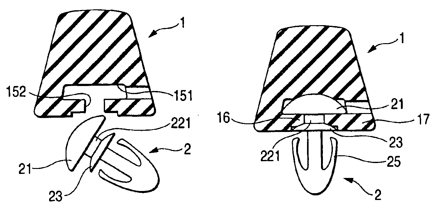
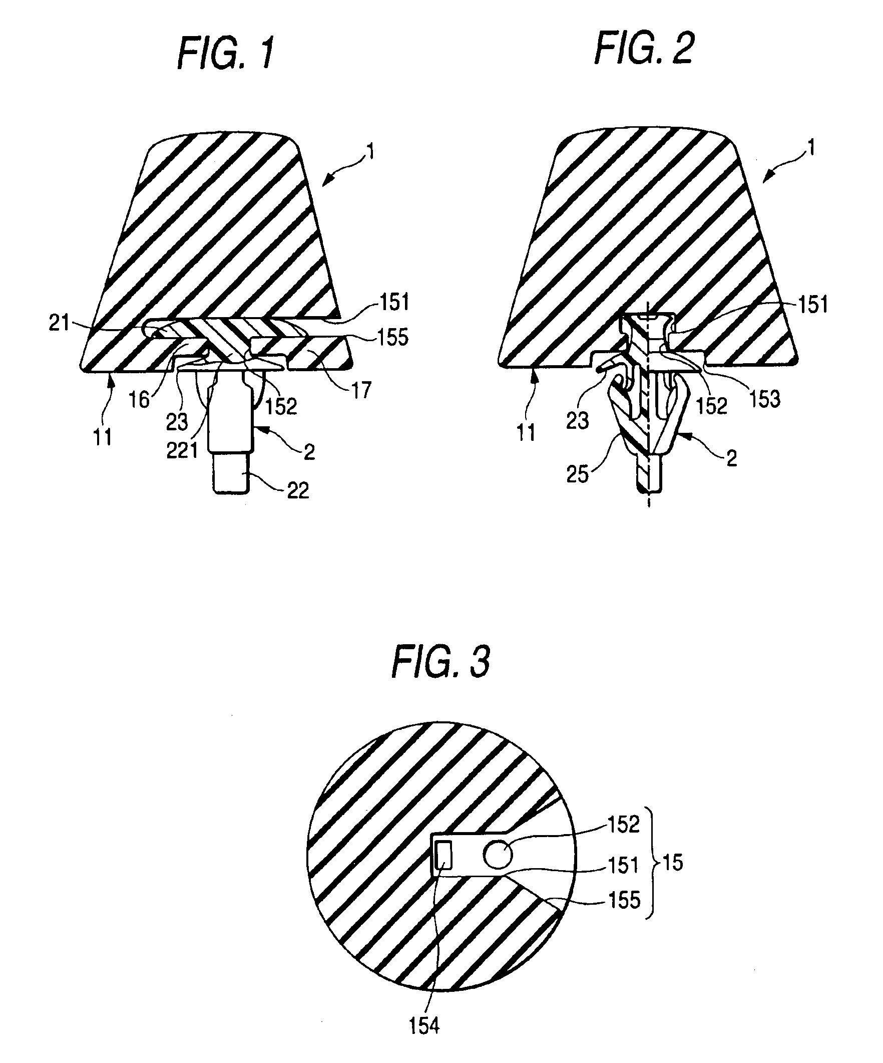
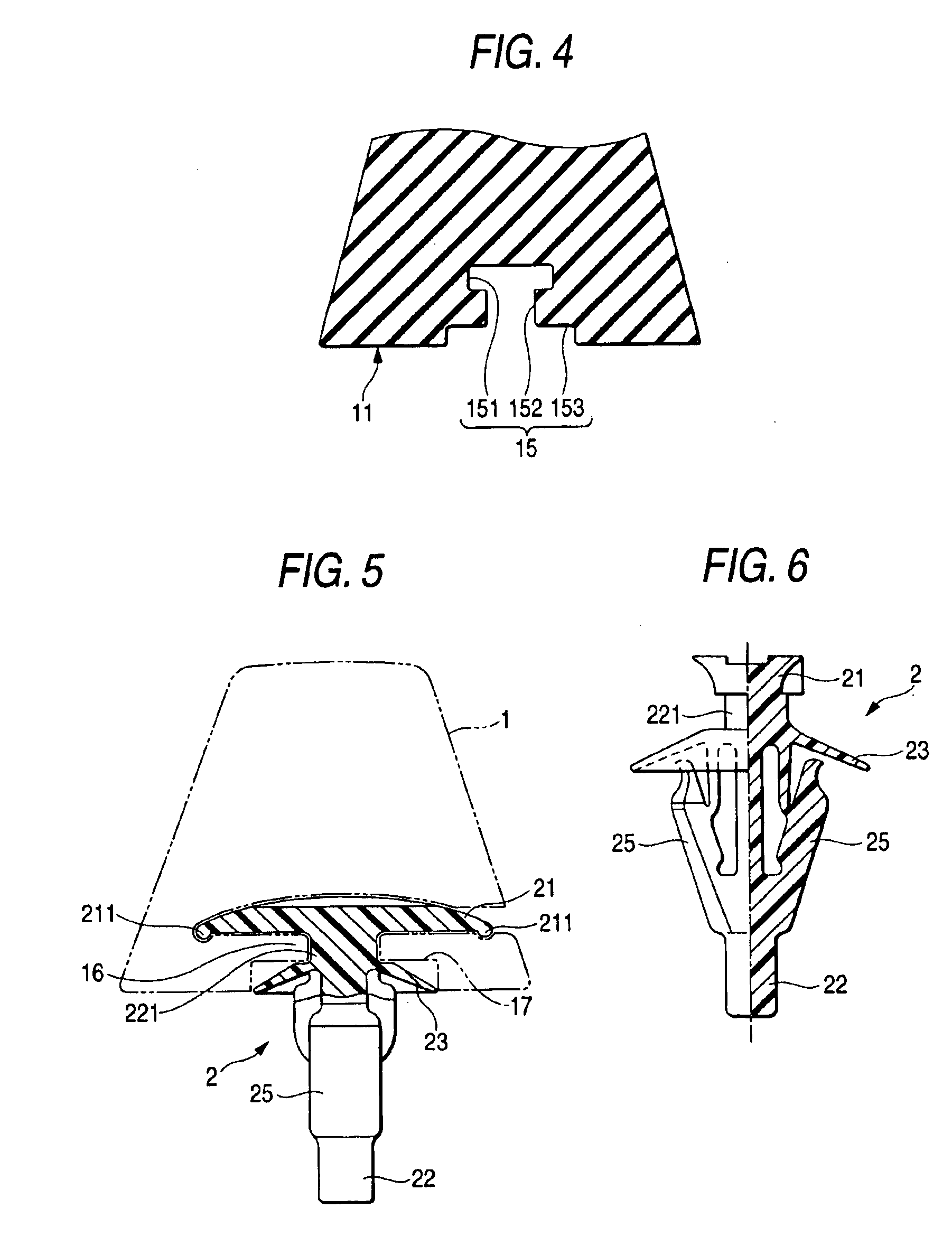
Hereinafter, a first embodiment of the invention is described with reference to FIGS. 1 to 8. As shown in FIGS. 1 and 2, this first embodiment is configured so as to basically comprise a cushion body 1, which is shaped like a frustum and made of a rubber material or an elastomer material, and also comprise a clip 2 that is provided in such a manner as to be erected from a bottom surface portion 11 of the frustum constituting the cushion body 1 and as to be used for mounting the cushion in a mounting hole 91 provided in a mounting member 9, and that is entirely formed from a predetermined plastic material.

Incidentally, the shape of the cushion body 1 is not limited to the frustum shown in FIG. 1 or 2, and may be other ones, such as a column and a distorted quadrangular pyramid shown in FIG. 8, as long as the cushion body of such a shape has an impact absorption function or a cushioning function. Further, as shown in FIGS. 1 and 2, the engagement holes 15, into each of which a corresp...

Example

Hereinafter, a second embodiment of the invention is described with reference to FIGS. 9 to 13. As shown in FIGS. 9 and 11, this second embodiment is configured in such a way as to basically comprise a cushion body 101 serving as stopper, and also has an engagement portion 102 provided in such a way as to be continued to the cushion body 101 and as to contribute to the mounting thereof onto a mounting member 109. Furthermore, this second embodiment further comprises a connecting portion 103 that is operative to connect between the engagement portion 102 and the cushion body 101 and that is formed in such a way as to easily bend and elongate. Further, these portions are integrally formed from rubber-like elastic elements.

In the cushion of such a basic configuration, the cushion body 101 is often shaped like a frustum. However, it is sometimes possible that the cushion body 101 is shaped like a column or a distorted quadrangular pyramid. Further, in the cushion body 101 of such a shap...


PUM


Abstract

A cushion body of a rubber-like elastic element having cushioning function in which engagement holes including a cave and a pit are formed. The cave is formed so that a horizontal head of a T-shaped clip is inserted into a space provided at the side of a bottom surface portion. The pit is formed so as to extend in a direction perpendicular to the cave, and to be opened in the bottom surface portion, permitting a vertical shaft of the clip to be inserted thereinto. The clip is formed with a plastic material and T-shaped and has a plurality of engaging claws flared toward the root portion from an end part of the vertical shaft of the T-shaped portion. The clip is engaged with the engagement holes of the cushion body.

Description

The present application is based on Japanese Patent Applications Nos. 2001-347165 and 2001-357004, the entire contents of which are incorporated herein by reference.BACKGROUND OF THE INVENTION1. Field of the InventionThis invention generally relates to a cushion provided on a door or a lid, and enabled to alleviate an impact force (or load) inputted to a door or a lid when such a door or a lid is closed. More particularly, this invention relates to an assembly type cushion consisting of two members, of which a cushion body is formed from a rubber member and which a clip portion constituting an engagement portion is formed from a plastic material having a predetermined stiffness so that the cushion excels in the mountability (or assemblability), and that the members of the cushion are prevented from dropping off therefrom after once assembled.2. Related ArtAs illustrated in, for example, FIG. 14, such a conventional cushion consists of a cushion body 110, which is shaped like a frust...

Claims


Application Information

Patent Timeline
IPC IPC(8): E05F5/02E05F5/00
CPCE05F5/022Y10T16/628Y10T403/4966E05Y2900/546F16F1/3732
Inventor NAKAGAKI, OSAMUIDO, YASUSHIHADANO, KATSUYA
Owner TOYODA GOSEI CO LTD
Why Eureka
Try Eureka