
Control system and method for internal combustion engine

Inactive Publication Date: 2005-02-22
HONDA MOTOR CO LTD
View PDF7 Cites 12 Cited by
  • Summary
  • Abstract
  • Description
  • Claims
  • Application Information

AI Technical Summary

Benefits of technology

With the arrangement of the control method according to the sixth aspect of the present invention, it is possible to obtain the same advantageous effects as provided by the fifth aspect of the present invention.
as provided by the fifth aspect of the present invention.
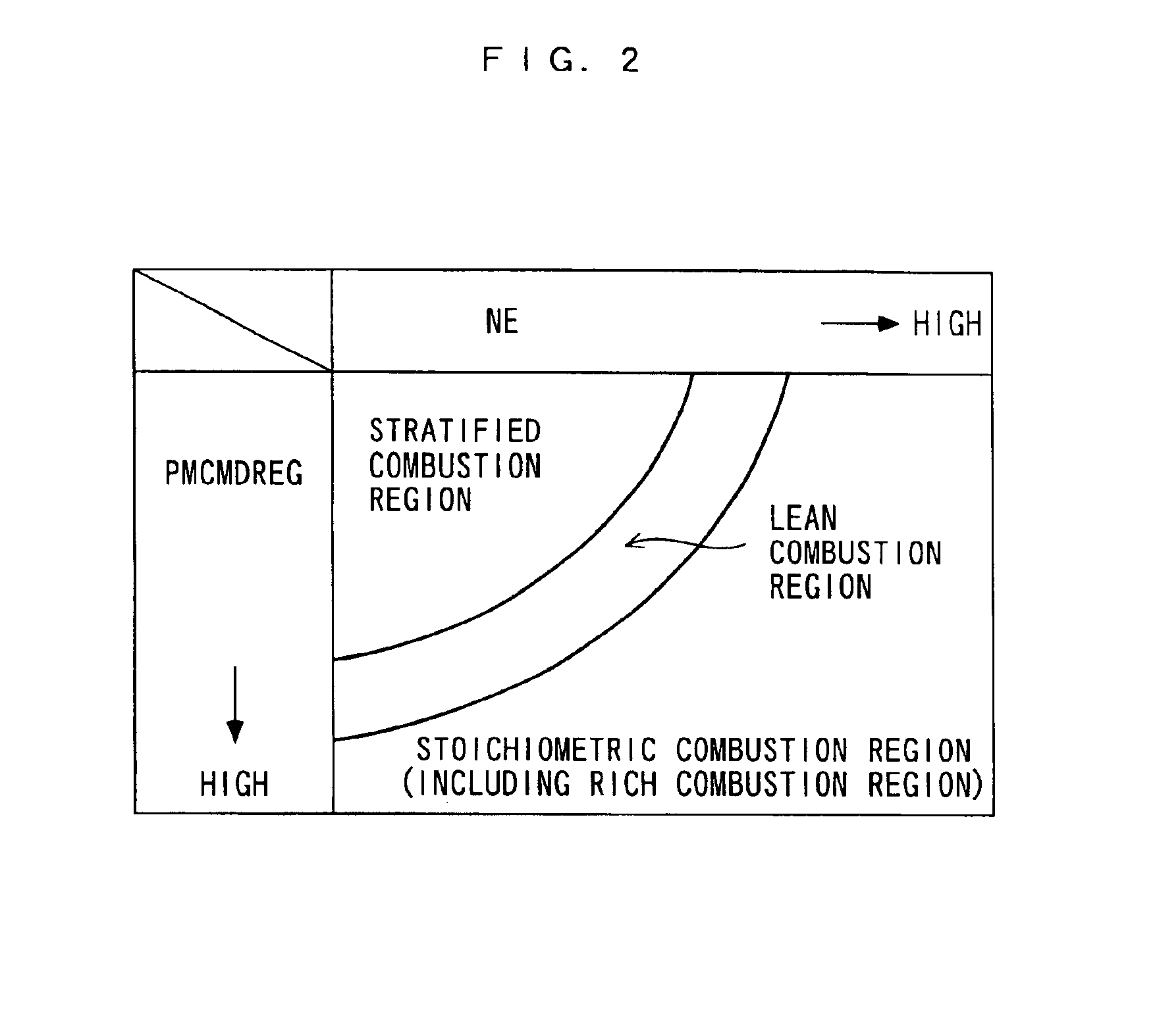
To attain the second object, in a seventh aspect of the present invention, there is provided a control method for an internal combustion engine of an in-cylinder injection type, which causes the engine to operate while switching a combustion mode thereof between a stratified combustion mode in which stratified combustion of a mixture is carried out and a homogeneous combustion mode in which homogenous combustion of the mixture is carried out, and at the same time controls a fuel injection amount based on a demanded fuel amount which is calculated.
The control method according to the seventh aspect of the present invention is characterized by comprising:
an operating condition-detecting step of detecting operating conditions of the engine;
a demanded fuel amount-calculating step of calculating the demanded fuel amount according to the detected operating conditions of the engine;

Problems solved by technology

However, the conventional control system described above suffers from the following problems: In the above method of calculating the fuel injection amount, when the combustion mode is switched, the fuel injection amount is calculated based on the immediately preceding value thereof, i.e. by multiplying the immediately preceding value by the ratio between the current and immediately preceding values of the torque correction amount and the ratio between the current and immediately preceding values of the basic fuel injection amount.
However, since the torque correction amount is merely increased or decreased by the fixed amount depending on which is larger, the rotational speed of the engine speed or the target value thereof, as described above, the ratio between the current and immediately preceding values of the torque correction amount does not correctly reflect a change in torque demanded of the engine dependent on a change in the rotational speed of the engine.
Further, since the basic fuel injection amount is a weighted average of the immediately preceding value and the current provisional value set according to the amount of intake air and the rotational speed of the engine, in short, an avaraged value, the ratio between the current and immediately preceding values of the basic fuel injection amount do not correctly reflect a change in the torque based on the amount of intake air and the rotational speed of the engine, either.
Therefore, the output torque of the engine obtained from the fuel injection amount calculated based on these parameters fails to agree with the demanded torque, which causes degradation of drivability.
Further, this control system provides the above-described control on the fule injection amount when the combustion mode is switched from the stratified combustion mode to the homonogeneous combustion but does not provide control when the combustion mode is switched in an opposite direction.
In such a case, it is impossible to properly control the output torque, which also leads to degraded drivability.

Method used


Image

  • Control system and method for internal combustion engine
  • Control system and method for internal combustion engine
  • Control system and method for internal combustion engine

Examples


Embodiment Construction

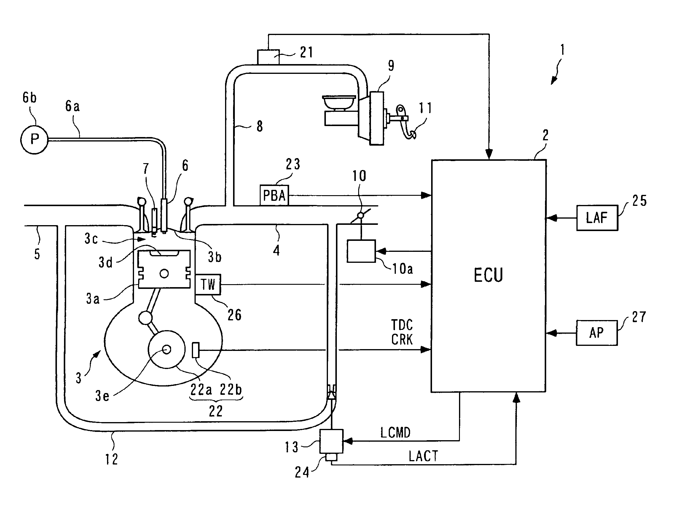
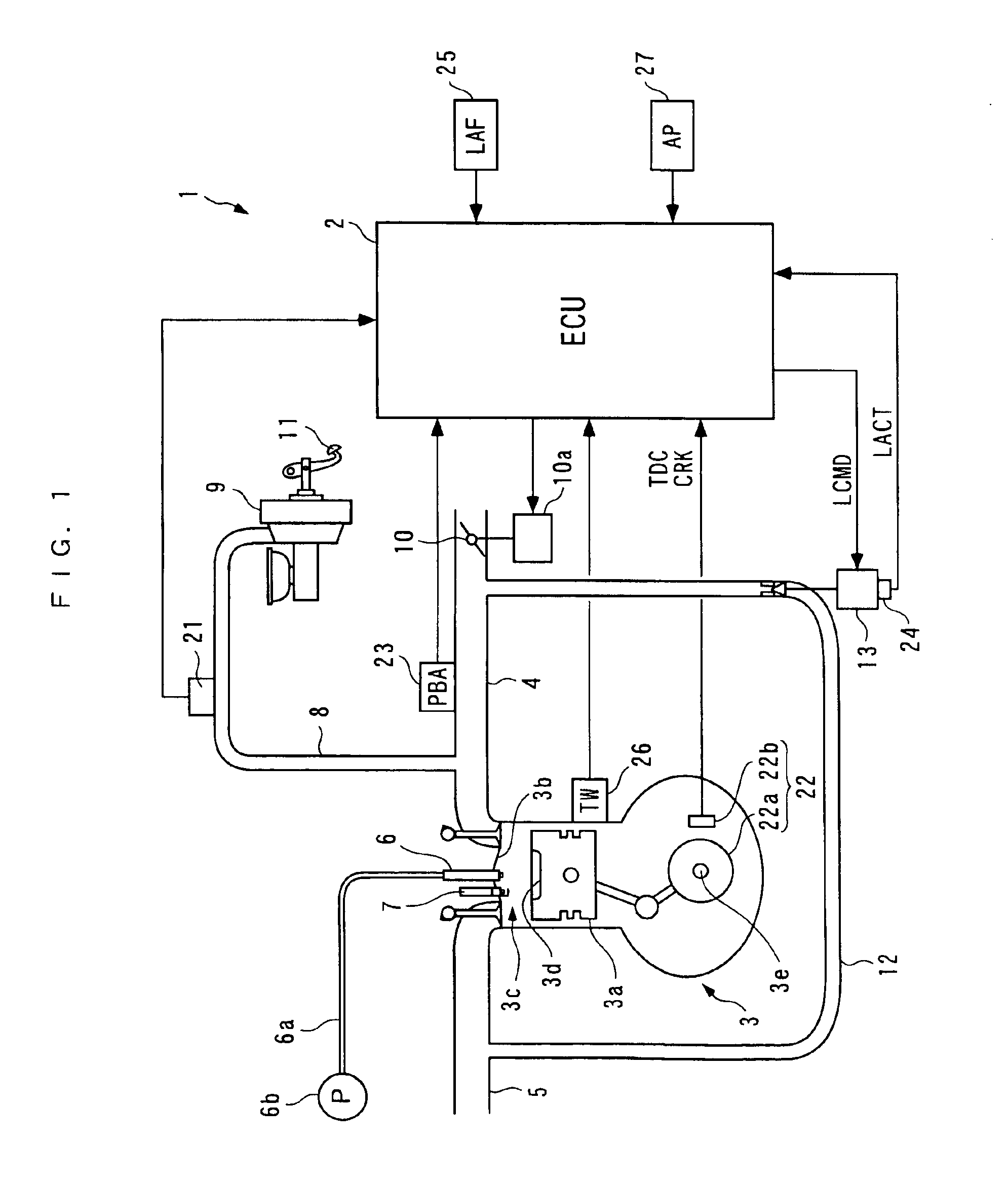
The present invention will now be described in detail with reference to the drawings showing a preferred embodiment thereof. FIG. 1 schematically shows the arrangement of a control system 1 according to the embodiment of the present invention and an internal combustion engine 3 (hereinafter simply referred to as “the engine 3”) to which the control system 1 is applied. The control system 1 includes an ECU 2.

The engine 3 is a straight type four-cylinder gasoline engine for a vehicle, not shown. The engine 3 has four cylinders (only one of which is shown) in each of which a combustion chamber 3c is defined between a piston 3a and a cylinder head 3b. The piston 3a has a central portion of a top surface thereof formed with a recess 3d. The cylinder head 3b has an air intake pipe 4 and an exhaust pipe 5 extending therefrom, as well as a fuel injection valve 6 (hereinafter simply referred to as “the injector 6”) and a spark plug 7 inserted therein in a manner facing each combustion chambe...


PUM


Abstract

There is provided a control system for an internal combustion engine, which is capable of matching an output torque of the engine with a demanded torque excellently when the combustion mode is switched, thereby enhancing drivability. A demanded fuel amount and a demanded torque of the engine are calculated according to detected operating conditions of the engine. A combustion mode is determined to be either the stratified combustion mode or the homogeneous combustion mode according to the demanded torque. A pre-switching demanded fuel injection time period and a pre-switching demanded torque are stored. When the combustion mode is switched, a switching-time demanded fuel amount (limit value) is calculated according to the stored pre-switching demanded fuel injection time period and pre-switching demanded torque, the current demanded torque, and an estimated combustion efficiency parameter.

Description

BACKGROUND OF THE INVENTION1. Field of the InventionThe present invention relates to a control system and method for an internal combustion engine of an in-cylinder injection type, which causes the engine to operate while switching the combustion mode of the engine between a stratified combustion mode and a homogeneous combustion mode and controls a fuel injection amount based on a calculated demanded fuel amount.2. Description of the Related ArtConventionally, a control system of the above-mentioned kind has been disclosed e.g. in Japanese Laid-Open Patent Publication (Kokai) No. 11-50895. According to this control system, even after the combustion mode of the engine installed on a vehicle is switched from the stratified combustion mode to the homogeneous combustion mode, some of a plurality of cylinders continue stratified combustion. In this case, the fuel injection amount for the cylinders that continue stratified combustion is set to a value calculated by multiplying the fuel i...

Claims


Application Information

Patent Timeline
IPC IPC(8): F02D41/12F02D41/30
CPCF02D41/123F02D41/3064F02D41/3029F02D2250/21F02D2041/389
Inventor OGAWA, KENKOMORIYA, ISAOTAGAMI, HIROSHITAKEUCHI, MASAHIROTORII, MINORUFUJIKI, YUJIMORISHITA, KUNIHIRO
Owner HONDA MOTOR CO LTD
Learn More