Storage package for coring reamer assembly

a technology of coring reamer and storage package, which is applied in the field of coring reamer, can solve the problems that the application is unaware of any prior related, and achieve the effect of reducing frictional interaction

Inactive Publication Date: 2005-02-22
LINVATEC
View PDF15 Cites 18 Cited by
  • Summary
  • Abstract
  • Description
  • Claims
  • Application Information

AI Technical Summary

Benefits of technology

(7) After the tunnel has been formed, the coring reamer is placed through the cap of the tube, with the adapter that coupled the coring reamer to the handpiece installed on the reamer and extending outside the package tube. A wrench is placed over the adapter and is turned while the user grips the peripheral surfaces of the cap to prevent rotation of the coring reamer, thereby allowing the adapter to be removed from the coring reamer. Thereafter, a plunger is inserted through the opening through the coring reamer from the proximal end thereof and is pushed therethrough until the bone core and bushing fall out of the distal end of the coring reamer and into the tube. Thereafter, the bone core may be removed and the coring reamer, bushing, tube and cap disposed of properly. It should be noted that the storage package can be used to initially couple the coring reamer / bushing assembly to the coupling adapter for assembly on to the handpiece.
It is a further object of the present invention to provide such a device in which the guide bushing engages an inner cylindrical passageway through the coring reamer with a line contact to reduce frictional interaction therebetween.

Problems solved by technology

Also applicants are not aware of any prior related to packaging suitable for storing coring reamers and usable thereafter to facilitate removal of a bone core from the reamer.

Method used


Image

  • Storage package for coring reamer assembly
  • Storage package for coring reamer assembly
  • Storage package for coring reamer assembly

Examples


Embodiment Construction

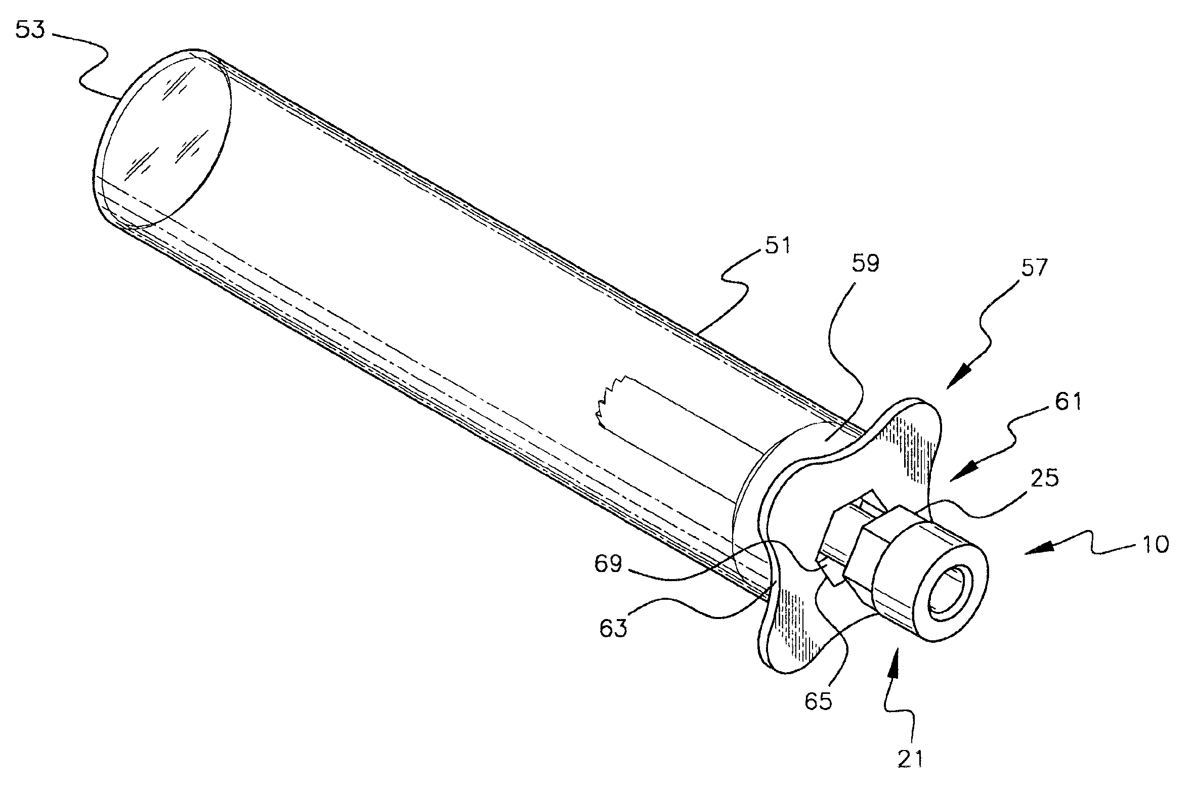
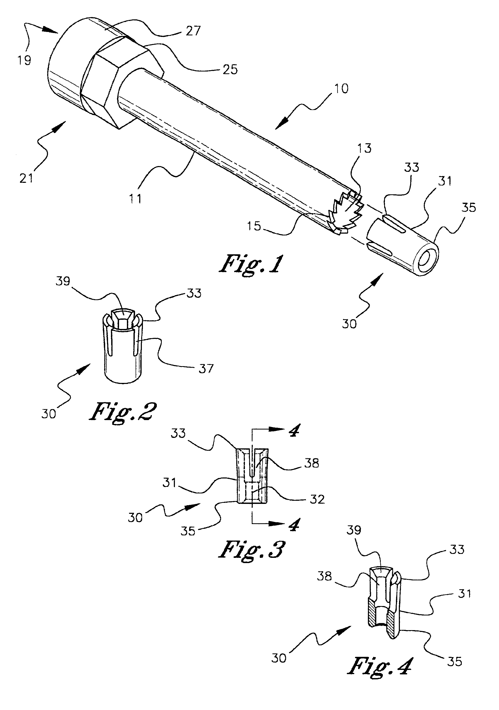
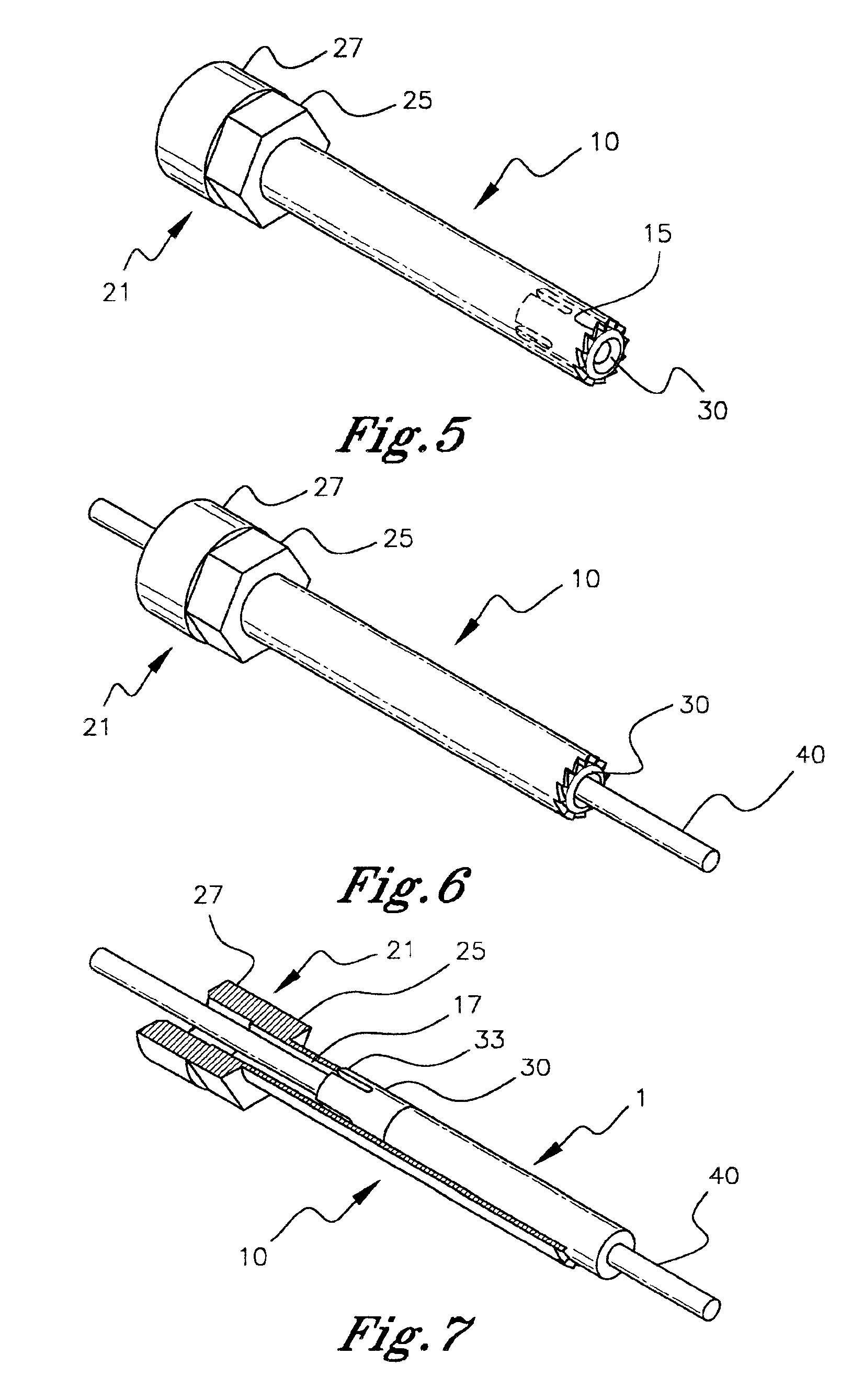
With reference, first, toFIGS. 1-6, a coring reamer is generally designated by the reference numeral 10 and is seen to include an elongated cylindrical tube 11 having an open distal end 13 surrounded by peripheral teeth 15. A cylindrical passageway 17 (FIG. 7) extends completely through the reamer 10.

With further reference to FIGS. 1-6, the reamer 10 includes a proximal end 19 consisting of a coupling 21 designed to couple the reamer 10 to an adapter 23 (FIG. 11) designed to couple the reamer 10 to a handpiece (not shown) adapted to rotate the reamer 10 in a manner well known to those skilled in the art. The proximal coupling 21 includes a distal portion 25 having a hexagonal periphery and a proximal portion 27 having a cylindrical periphery. The interface between the adapter 23 and the proximal coupling 21 consists of a threaded interconnection (not shown).

With particular reference to FIGS. 1-4, a flared bushing is generally designated by the reference numeral 30 and is seen to inc...


PUM


Abstract

A guide bushing for a coring reamer having a tapered member with its largest diameter at its first end so that the guide bushing frictionally engages an internal surface of the reamer with a line contact. The guide bushing has a passage sized to slidably receive a guide pin. In use, the bushing advances in the proximal direction within the coring reamer along a guide pin while the excavated bone enters the passageway through the reamer. A storage package specifically designed for the reamer assembly is employed to remove the excavated bone from within the reamer. The package has a closed distal end and an open proximal end closeable with a cap. With the coring reamer received in cantilevered fashion through a central opening of the cap of the tube, and with an adapter that couples the coring reamer to a handpiece installed, a wrench is placed over the adapter and turned while the user grips peripheral surfaces of the cap to prevent rotation of the coring reamer. A plunger is inserted through the opening through the coring reamer from the proximal end and is pushed through the reamer until the bone core and bushing fall out of the distal end of the coring reamer.

Description

BACKGROUND OF THE INVENTIONThe present invention relates to a coring reamer. More particularly, it refers to an improved guide bushing for a coring reamer, a storage package for a coring reamer assembly, and a method of using the coring reamer.In the prior art, it is well known to use a coring reamer to cut a cylindrical bone tunnel at a surgical site. The reamer is coupled to a handpiece that rotates the reamer to facilitate cutting a bone tunnel. For this purpose, the reamer has a cylindrical distal end with sharp teeth formed thereon.It is also well known to guide such a reamer by employing a guide pin separately and previously driven into or through the bone at the surgical site. As the reamer cuts the bone tunnel, the reamer slides over the guide pin to guide its motion. While the prior art contemplates an interface between the guide pin and the reamer, one aspect of the present invention proposes an improvement thereover.In U.S. Pat. No. 5,423,823 to Schmieding, the guide pin ...

Claims


Application Information

Patent Timeline
Patent Type & Authority Patents(United States)
IPC IPC(8): A61B17/16A61B19/02A61B19/00
CPCA61B17/1637A61B19/026A61B2019/0213A61B19/0262A61B50/30A61B50/3001A61B2050/006
Inventor SALAZAR, BARTOLOME J.BRASFIELD, ANDREABELLAFIORE, MARK A.
Owner LINVATEC
Why Eureka
Try Eureka