LED work light

a technology for working lights and led light bulbs, which is applied in the direction of hand-held electric lighting, signalling/lighting devices, and light support devices. it can solve the problems of low light output, low heat output, and fragile filament in these light bulbs, and achieve low power. the effect of low amount of hea

Inactive Publication Date: 2005-02-22
GENERAL MFG
View PDF31 Cites 204 Cited by
  • Summary
  • Abstract
  • Description
  • Claims
  • Application Information

AI Technical Summary

Benefits of technology

One advantage of the present invention is that LEDs have a life which is much longer than the life of a fluorescent or incandescent lamp. Further, recently available LEDs require a relatively low amount of power while producing an amount of light comparable to incandescent lamps, while producing a low amount of heat.

Problems solved by technology

A problem with work lights having incandescent lamps is that the filament in these light bulbs is fragile and may break relatively easily.
A further problem with incandescent lamps is that they emit a substantial amount of heat.
A problem with fluorescent lamps is that the glass of the tube may be thin and thus fragile.
Other problems with fluorescent work lights are that the leads may tarnish or become loose in the socket, thereby breaking the electrical connection.
Another problem with fluorescent work lights is that these types of lights require a relatively significant amount of voltage to operate.
If battery operated, several batteries may be required to properly energize the lamp of the fluorescent work light making the work light heavy and cumbersome.
LED lamps have conventionally not produced a sufficient amount of light so that they could be used in work lights and the like.

Method used


Image

  • LED work light
  • LED work light
  • LED work light

Examples


second embodiment

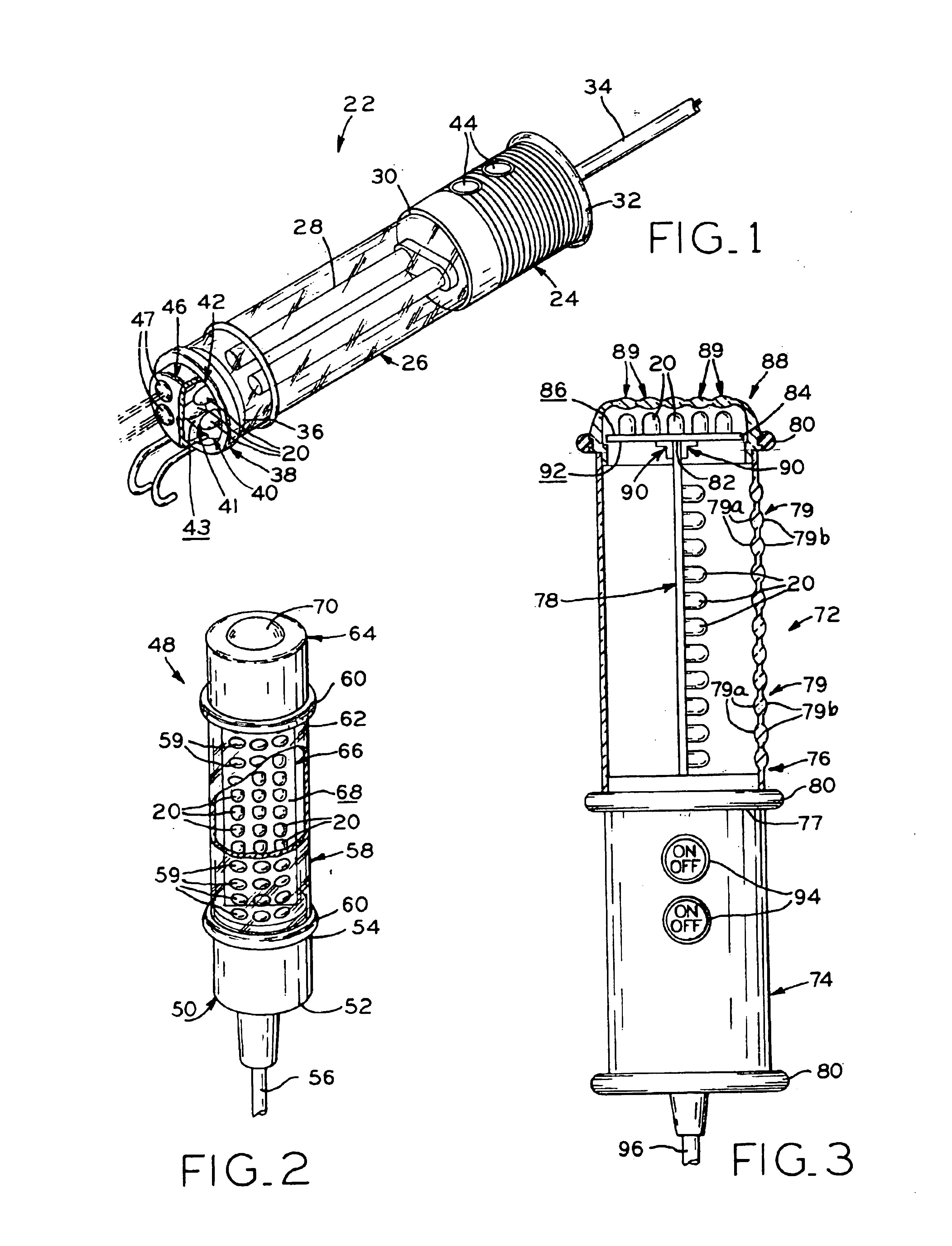
Referring to FIG. 2, a work light in accordance with the present invention is shown. Work light 48 includes handle 50 having ends 52 and 54 with power cord 56 extending from end 52. Secured to end 54 of handle 50 is transparent cover 58. A portion of cover 58 shown in FIG. 2 is broken away for illustration purposes. Handle 50 and cover 58 may be constructed by any suitable method such as injection molding or blow molding. As with handle 24 and cover 26 of work light 22, handle 50 may be formed from any suitable material including plastic or metal. The material used for cover 26 may also be any suitable material including plastic or glass. Disposed at both ends of cover 58 are rubber bumpers 60 which are designed to protect work light 48 from damage if the light were dropped, for example. Cover 58 is provided with a plurality of transparent dome shaped or convex lenses 59. One lens 59 is located directly above each LED 20 to magnify and focus the light emitted therefrom. Lens 59 is i...

third embodiment

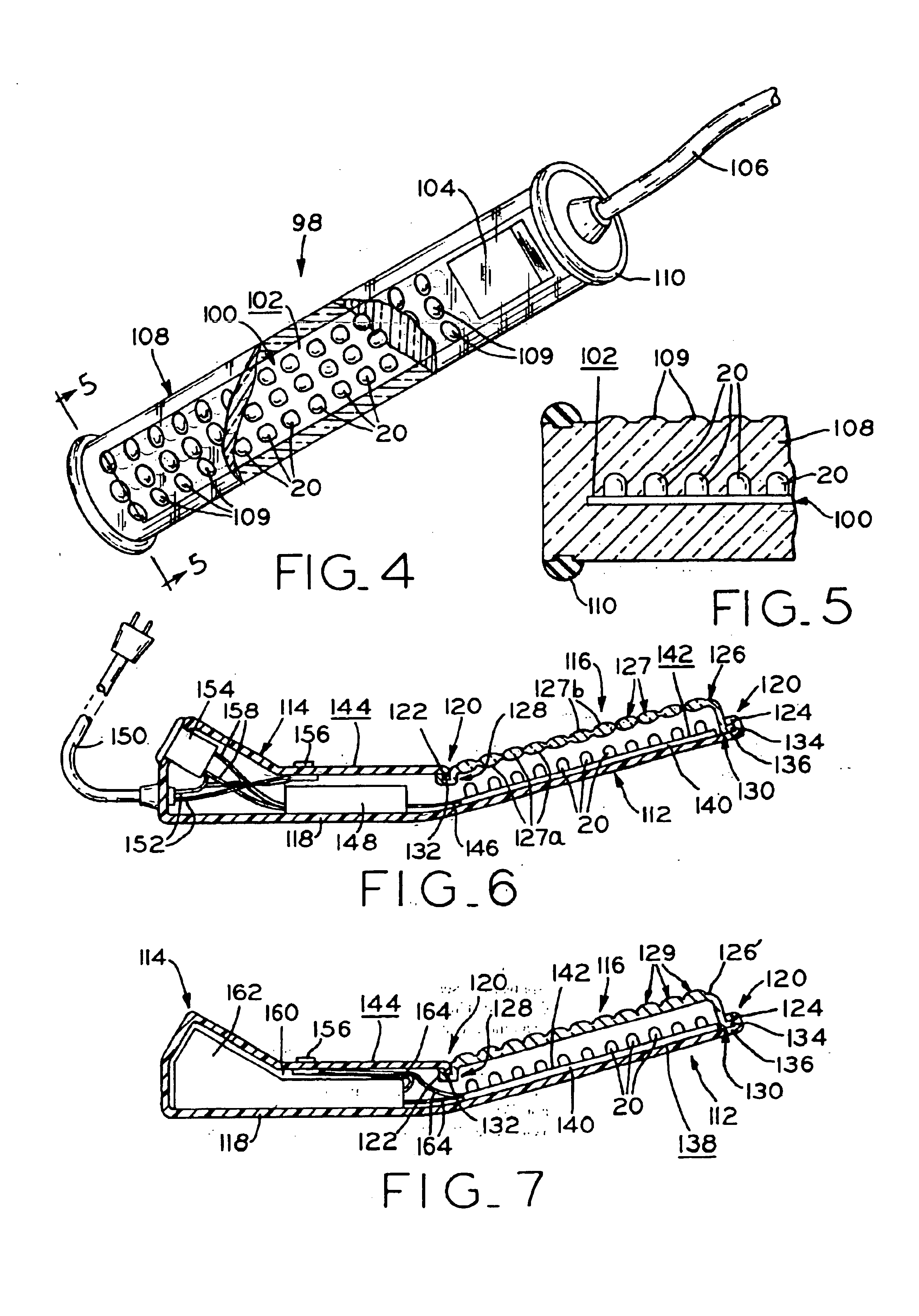
FIGS. 4 and 5 disclose a work light in accordance with the present invention. Submersible work light 98 includes circuit board 100 having a plurality of LEDs 20 mounted on surface 102 thereof in the same manner as discussed above. Power regulator 104 is disposed at one end of circuit board 100 to transform the input voltage from the power source into the appropriate operating voltage for LEDs 20 and circuit board 100 of which they are a part. In this embodiment, the input power is 120 volts from an electrical outlet through power cord 106. Solid, transparent casing 108 is molded around circuit board 100, LEDs 20, power regulator 104, and the end of cord 106. Rubber bumpers 110 are secured to each end of casing 108 to protect work light 98 from damage. Casing 108 is molded about circuit board 100, LEDs 20, power regulator 104, and the end of cord 106 to allow work light 98 to be submersible or waterproof. The material used to encase the components of work light 98 may be of any suita...

fourth embodiment

a work light in accordance with the present invention is illustrated in FIGS. 6 and 7. Work light 112 includes handle portion 114 and light head portion 116 which is disposed at a slight angle relative to handle portion 114. Work light 112 is constructed such that casing 118 completely surrounds handle portion 114 and extends along the backside of light head portion 116. Casing 118 may be constructed from any suitable material including plastic or metal by any suitable method such as molding. Terminating ends 120 of casing 118 are molded to define hook-like projections 122 and 124. Transparent cover 126 is positioned over circuit board 140 carrying LEDs 20 and has ends 128 and 130. Cover 126 may be plastic, glass, or the like which is formed by any suitable method. End 128 is C-shaped such that hook-like projection 122 fits into space 132 formed by the C-shaped end. End 130 is L-shaped such that leg 134 of end 130 engages space 136 of hook-like projection 124. The connections betwee...


PUM


Abstract

A work light for work or task areas which uses light-emitting diodes (LEDs) as the source of light. LED clusters are mounted on a circuit board which is located in a housing. The LED work lights may be powered by conventional 120 or 240-volt electrical outlets, a DC generator, a battery, a battery pack, or a car adapter.

Description

BACKGROUND OF THE INVENTIONThe present invention relates to work lights used to illuminate task or work areas.Conventionally, fluorescent or incandescent work lights are used to provide light in work areas. Such lights need to be relatively compact and portable. Work lights conventionally include a handle for gripping the light and a fluorescent or incandescent lamp for providing light to an area. The lamp may be at least partially covered by a transparent cover. The work light may include a cord and plug for connection to an electrical outlet. Alternatively, the work light may be battery operated.Incandescent lamps have a thin filament which is energized to emit light when the work light is supplied with electrical current. A problem with work lights having incandescent lamps is that the filament in these light bulbs is fragile and may break relatively easily. The life of an incandescent bulb is determined by the length of time the filament stays intact as, once the filament breaks...

Claims


Application Information

Patent Timeline
Patent Type & Authority Patents(United States)
IPC IPC(8): F21L14/02F21L4/08F21L14/00F21L4/00F21L4/04F21V5/00F21K99/00F21S8/00F21V5/04F21V21/096F21V21/32F21V31/04
CPCF21L4/04F21K9/58F21L14/023F21V5/04F21V21/0965F21V21/32F21V31/04F21L4/08F21S8/033F21V5/006F21Y2101/02F21Y2103/00F21Y2113/00F21Y2113/02Y10S362/80F21V5/007F21V21/08F21Y2105/001F21K9/13F21K9/23F21K9/65F21V5/10F21Y2105/10F21Y2113/20F21Y2115/10
Inventor REIFF, PAUL J.REIFF, DAVID L.BROWN, CLYDE M.
Owner GENERAL MFG
Why Eureka
Try Eureka