

Support member for an assembly
a technology of supporting member and assembly, which is applied in the direction of insulated conductors, cables, relatively moving parts, etc., can solve the problems of affecting the mechanical precision of the assembly, affecting the flexibility, speed and power requirements of the manufacturing equipment, and affecting the quality of the assembly. , to achieve the effect of low mechanical noise, high degree of flexibility and small bend radius
- Summary
- Abstract
- Description
- Claims
- Application Information
AI Technical Summary
Benefits of technology
Problems solved by technology
Method used
Image

Examples
example 1
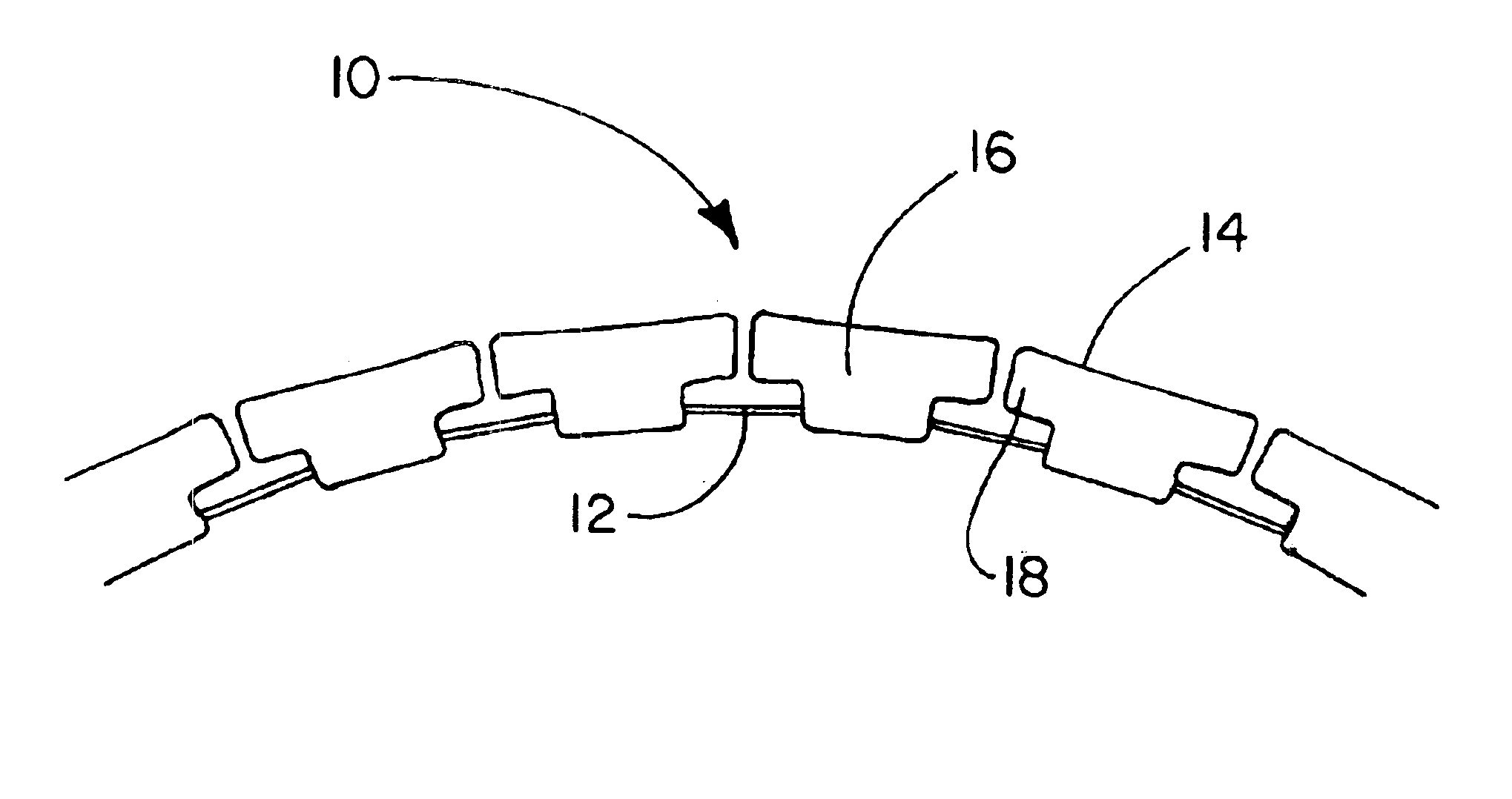
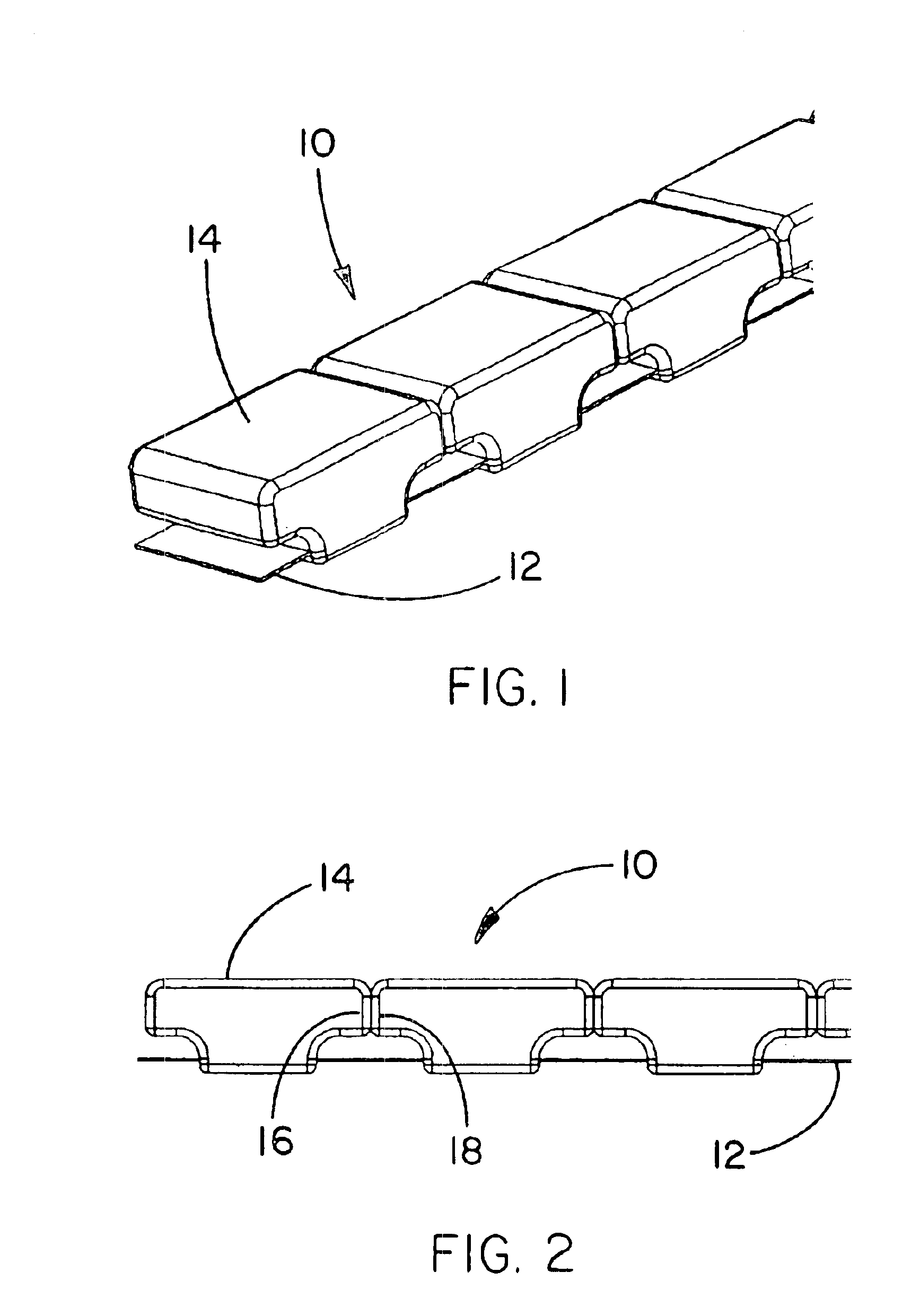
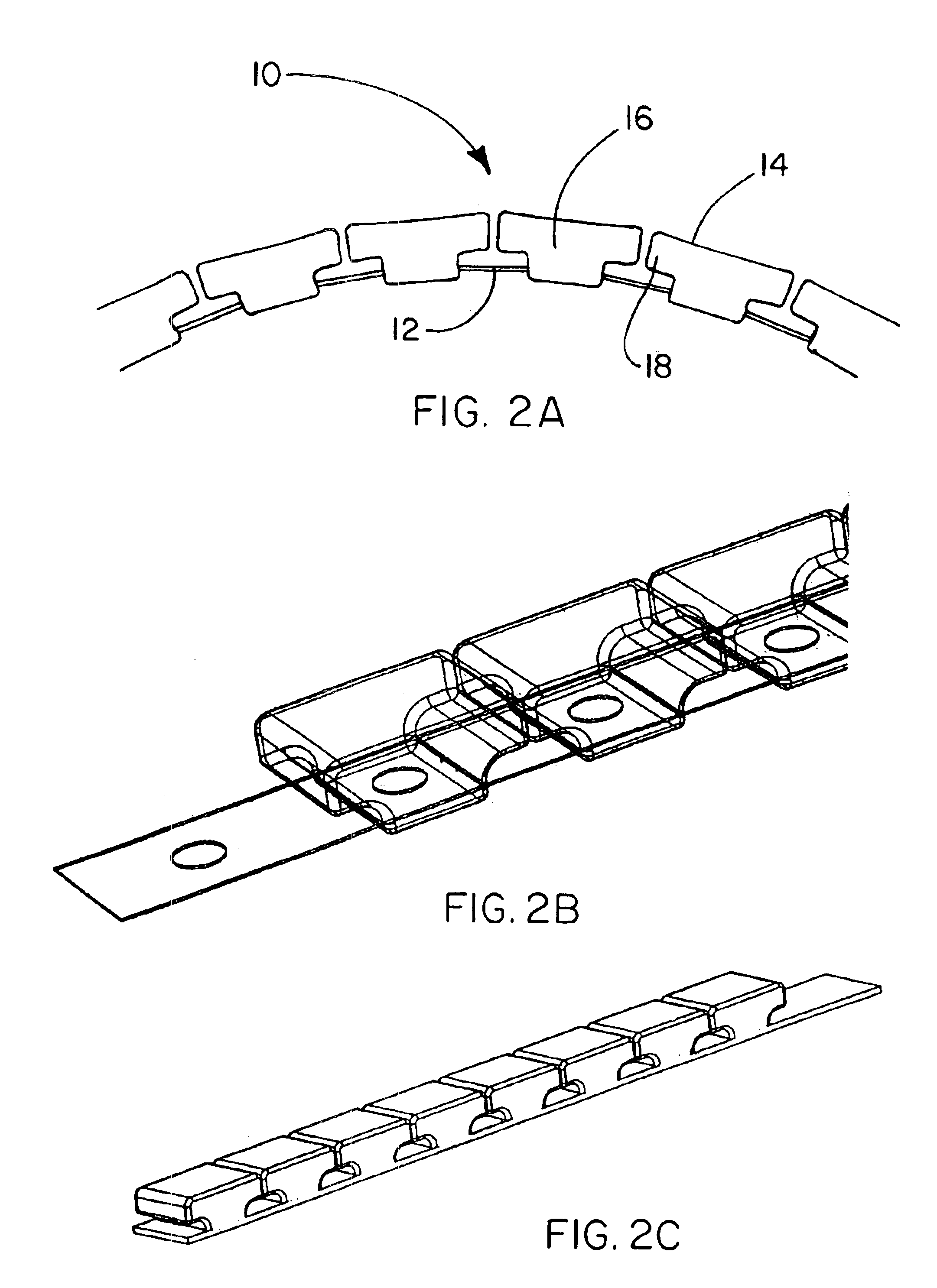
This example describes the construction of a support member of the present invention as illustrated in FIGS. 1-2.
A length of flexible material in the form of 301 High Yield Stainless Steel, 0.25 inches wide and 0.005 inches thick was obtained from Belt Technologies, Inc., Agawam, Mass. A series of holes 0.093 inches in diameter were stamped in the stainless steel. The holes were spaced 0.385 inches apart. The stainless steel was then placed in an insert mold in preparation for attaching of a plurality of non-interlocking, motion-limiting, solids to the stainless steel. The insert mold was provided with a form for the solids having an overall shape and profile as illustrated in FIGS. 1 and 2, respectively. An over-molding technique was used to simultaneously form and attach the solids to the stainless steel. The stainless steel was maintained in a curved configuration in the mold to provide space between each individual solid as the solids were formed and attached to the stainless st...
example 2
This example describes the construction of a support member of the present invention as illustrated in FIGS. 3-4.
The materials and methods of this example are the same as those described in Example 1 except for the overall shape and profile of the non-interlocking, motion-limiting, solids. The overall shape and profile of the solids formed in this example are illustrated in FIGS. 3 and 4, respectively.
example 3
This example describes the construction of a support member of the present invention as illustrated in FIGS. 5-7.
The materials and methods of this example are the same as those described in Example 1 except for the shape and profile of the non-interlocking, motion-limiting, solids. The overall shape of the solids formed in this example is illustrated in FIGS. 5-6. The profile of the solids is illustrated in FIG. 7. The solids of this example have non-interlocking projections and concavities in mateable relationship. These features serve as means for maintaining linear alignment of the support member.
PUM
 Abstract
Description
Claims
Application Information