Method and device for retracting an actuator

a technology of actuator and actuator arm, which is applied in the direction of data recording, instruments, and recording head arrangements, etc., can solve the problems of stiction affecting the read/write head, and the actuator arm, and the ramp presents additional resistance to the movement of the actuator arm, so as to achieve constant retraction speed, increase or decrease the effect of the retraction speed and the constant retraction speed

Inactive Publication Date: 2005-02-22
SEAGATE TECH LLC
View PDF34 Cites 22 Cited by
  • Summary
  • Abstract
  • Description
  • Claims
  • Application Information

AI Technical Summary

Benefits of technology

In accordance with still other embodiments of the present invention, a rectifier may rectify the AC currents generated in the coils of the spindle motor. The resulting current, which may be referred to as a “control current,” is supplied to an H-bridge circuit responsible for applying the control current to the coil of the VCM. As the control current is applied to the coil, an electric field is generated around the coil that interacts with the magnetic field of the VCM to produce movement by the actuator assembly, and thus the read / write heads. The direction that the current enters the coil controls whether the rate of displacement by the heads is either accelerated or decelerated toward the non-data locations.
At times when the control current is in a zero magnitude phase, a back electromotive force (VVCM) is generated across the coil of the VCM as the read / write heads continue to retract toward the data regions. VVCM may be measured and input to a control system to determine whether the rate of positional displacement by the read / write heads should be accelerated or decelerated in order to maintain the retract velocity about the desired retract velocity. As such, VVCM may be compared to a threshold voltage (VTH) representative of the desired retract velocity. If VVCM is less than VTH, the control current may be applied by the H-bridge circuit in an opposite direction through the coil than if VVCM is greater than VTH. Thus, the H-bridge circuit effectively maintains a constant retract velocity of the read / write heads by allowing current to flow through opposite directions in the coil as the heads are being retracted toward the non-data locations. By allowing this bi-directional flow of current through the coil, the positional displacement of the actuator arms, and thus the read / write heads, may be accelerated or decelerated, thereby resulting in increasing or decreasing velocity, respectively toward non-data locations on or in close proximity to the discs. By controlling the velocity in this manner, the present invention retracts the read / write heads across the discs about the desired retract velocity in accordance with an embodiment of the present invention. Such a relatively constant retract velocity may be achieved by relatively slowly changing torque profiles that effectively minimize the vibration of components of the disc drive thereby resulting in lower levels of acoustical noise in the disc drive.

Problems solved by technology

However, contact between a read / write head and the disc surface can damage the magnetizable medium and the head.
Stiction can damage the magnetizable medium, the read / write head, and / or the actuator arm when the disc drive system initiates disc rotation in an attempt to move the read / write head from the disc surface.
Furthermore, the ramp presents additional resistance to the movement of the actuator arm, because the arm must ascend the sloped surface of the ramp, which also introduces an additional friction component.
As such, a relatively high retract velocity may result in hard errors on one or more data regions on the discs.
While these conventional systems may accomplish the task of limiting the retract velocity of the read / write heads across the discs, they are not without problems.
First, the circuitry employed in conventional velocity limiting actuator retract systems is often complex in design.
As such, these conventional systems are not only expensive to design and manufacture, but are associated with routine implementation errors that may be harmful to the overall operation of the disc drive.
Second, transition into and out of the VVCM sampling period by this circuitry involves unnecessarily large and steep transitions in the VVCM waveform versus time, thereby resulting in irregular rates of torque applied to the actuator arms over time.
These irregular rates in torque often excite components within the disc drive thereby causing the components to vibrate, which results in undesirable high levels of acoustical noise in disc drives.

Method used


Image

  • Method and device for retracting an actuator
  • Method and device for retracting an actuator
  • Method and device for retracting an actuator

Examples


first embodiment

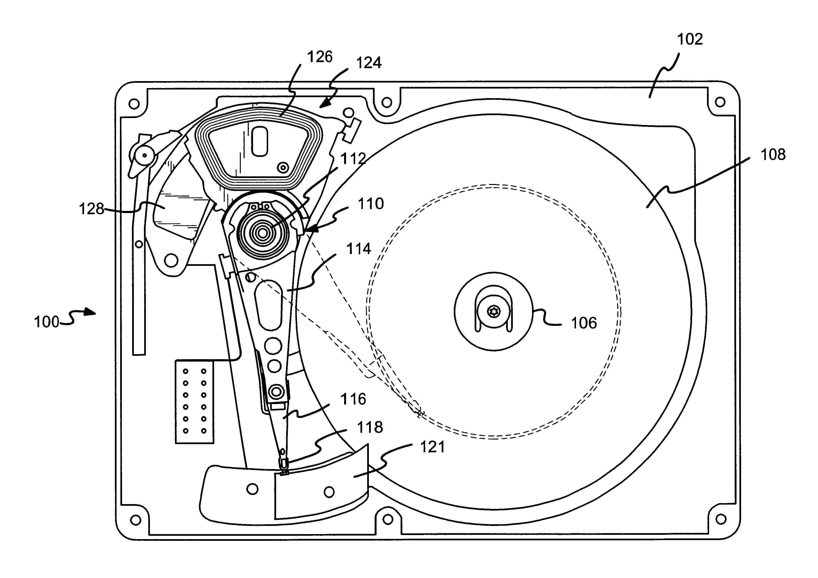
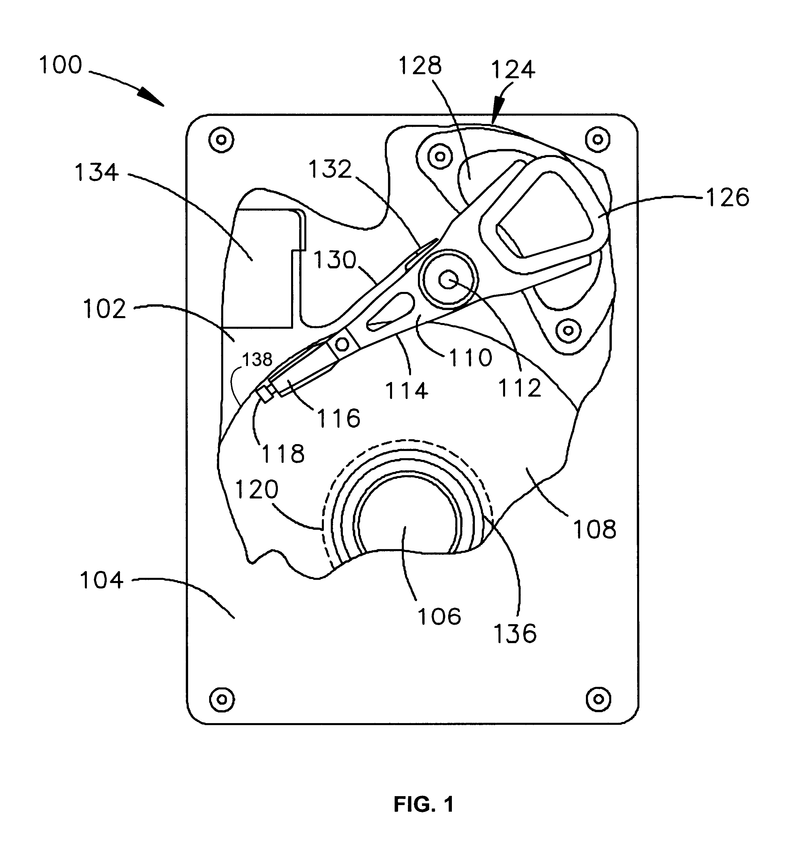
In accordance with a first embodiment shown in FIG. 1, the disc 108 may include one or more landing zones 120 for parking the read / write head 118 while the drive 100 is de-energized. As such, the head 118 is prevented from inadvertently contacting the surface of the disc 108 while the disc 108 is stationary. The use of a landing zone 120 to disengage a head 118 from data regions 304 on the surface of the disc 108 is commonly found in disc drives 100 administering a contact start / stop technique. With respect to the contact start / stop technique, the servo control system 150 controls the actuator 114 such that the slider contacts the landing zone 120 during start and stop operations when there is insufficient rotational speed to maintain the air bearing between the surface of the disc 108 and the slider. The landing zone 120 may be a dedicated radial region on the disc 108 that is specially textured to minimize the effect of stiction, which is static friction between a very smooth disc...

second embodiment

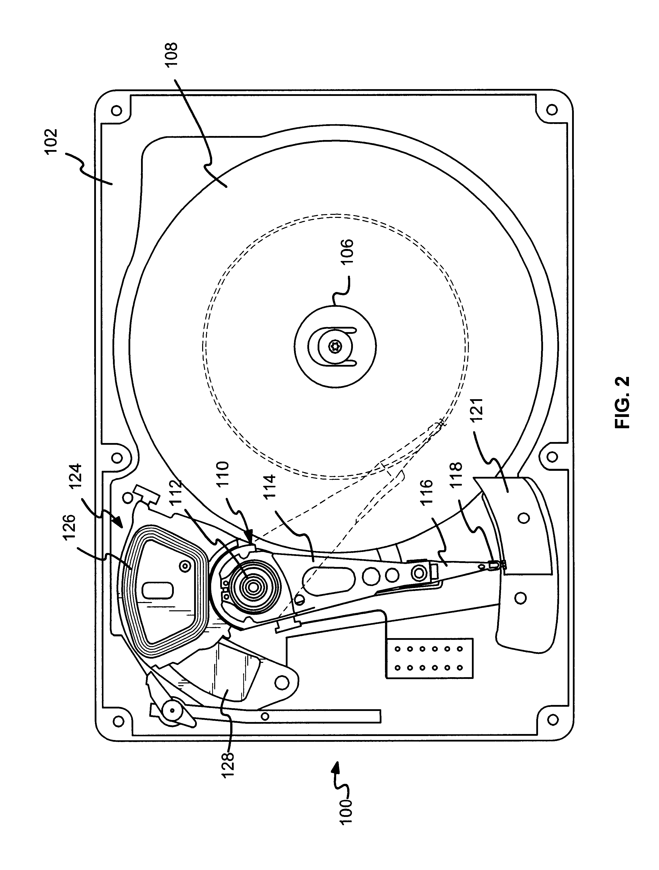
In accordance with a second embodiment shown in FIG. 2, the disc 108 may include a load / unload ramp 121 for parking the read / write heads 118 off the surface of the disc 108 while drive 100 is de-energized. A load / unload ramp 121 prevents the read / write head 118 from inadvertently contacting the surface of the disc 108 while the disc 108 is rotating at a speed insufficient for maintaining the air bearing between the surface of the disc 108 and the slider. In a disc drive 100 utilizing a load / unload ramp 121, the read / write head 118 is mechanically unloaded from the disc 108 by the servo control system 150 at power-down. The head 118 is then loaded back to the disc 108 when the disc 108 has reached a rotational speed sufficient to generate the air bearing.

Referring now to FIG. 4, shown therein is a functional block diagram of the disc drive 100 shown in FIGS. 1 and 2 generally showing the main functional components which are resident on the disc drive printed circuit board and used to...


PUM

PropertyMeasurementUnit
currentaaaaaaaaaa
open-circuit voltageaaaaaaaaaa
velocityaaaaaaaaaa

Abstract

An actuator retract system and method for moving read/write heads from data regions on discs to non-data locations in a disc drive is disclosed. The non-data locations may be on or in close proximity to the discs. The non-data locations may be a landing zone or a load/unload ramp. At disc drive power-down, power generated from the rotational inertia in rotating discs is used to supply a current to a coil of a voice coil motor operably coupled to the actuator. During such power-down operation, a desired velocity is maintained using acceleration or deceleration, when necessary. The current generates an electric field around the coil that interacts with a magnetic field in the voice coil motor to move the actuator such that the read/write heads are retracted to the non-data location.

Description

FIELD OF THE INVENTIONThis application relates generally to data storage devices and more particularly, but not by way of limitation, to supplying power from a spindle motor to an actuator assembly in a disc drive system.BACKGROUND OF THE INVENTIONModern hard disc drives comprise one or more rigid discs that are coated with a magnetizable medium and mounted on a spindle hub of a spindle motor for rotation at a high speed. Information is read from and written to each disc in a plurality of concentric tracks by a read / write head mounted on an actuator arm. The outside circumference of each disc is referred to as the “outer diameter” (OD), and the region of each disc near the spindle hub is referred to as the “inner diameter” (ID). A read / write head is said to “fly” over the disc surface as the disc rotates. When disc rotational velocity decreases, the layer of air supporting read / write head above the disc surface diminishes and the head descends toward the disc surface. However, conta...

Claims


Application Information

Patent Timeline
Patent Type & Authority Patents(United States)
IPC IPC(8): G11B21/12G11B5/54
CPCG11B21/12G11B5/54
Inventor BRITTNER, RODNEYTHROCKMORTON, PAUL J.
Owner SEAGATE TECH LLC
Why Eureka
Try Eureka