Nodal mounted system for driving a power appliance

a technology of power appliances and drive systems, which is applied in the direction of mechanical energy handling, cleaning equipment, carpet cleaners, etc., can solve the problems of affecting the the dynamic of the handle and the resulting performance of the device, and vibration coupled to the device handl

Inactive Publication Date: 2005-03-01
KONINKLIJKE PHILIPS ELECTRONICS NV
View PDF7 Cites 42 Cited by
  • Summary
  • Abstract
  • Description
  • Claims
  • Application Information

AI Technical Summary

Problems solved by technology

Resonant devices, using a motor with a rotating armature, often have the advantages of design simplicity and reasonable cost, as well as generally a small size, but also have significant disadvantages, including vibration coupled to the handle of the device caused by the reversing action of the system as it oscillates back and forth through the selected arc, instead of rotating continuously through a 360° rotation.
Performance of the device is also affected by the dynamics

Method used


Image

  • Nodal mounted system for driving a power appliance
  • Nodal mounted system for driving a power appliance
  • Nodal mounted system for driving a power appliance

Examples


Embodiment Construction

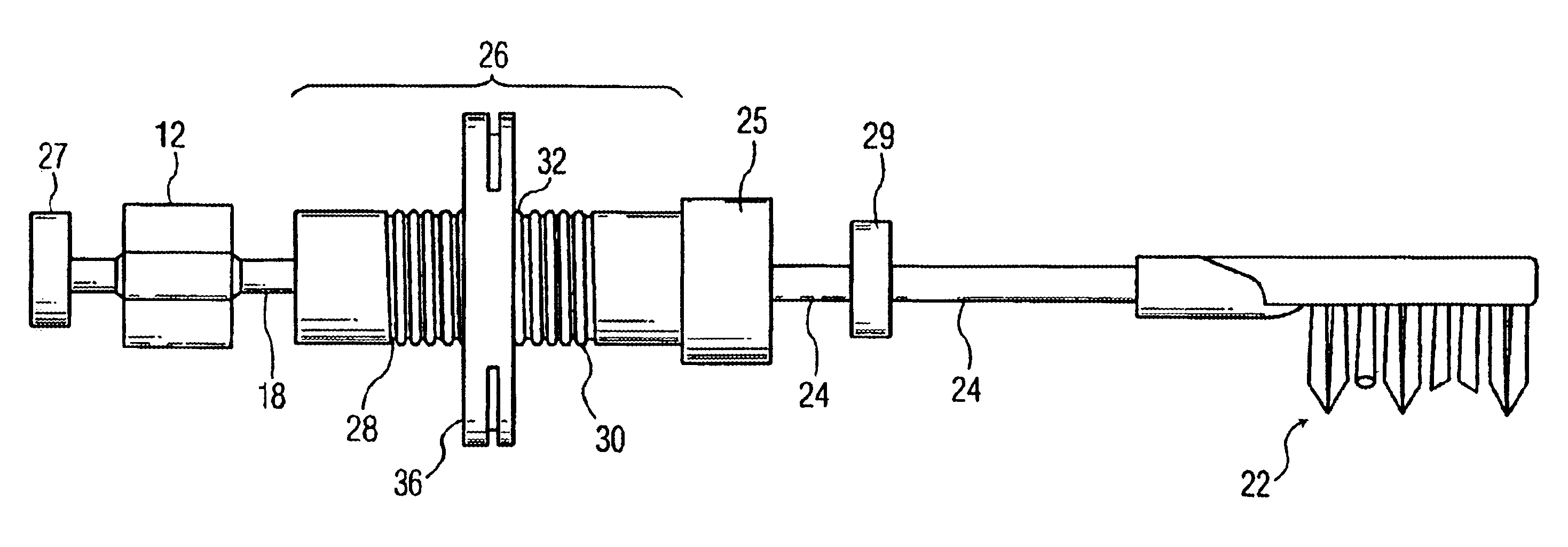
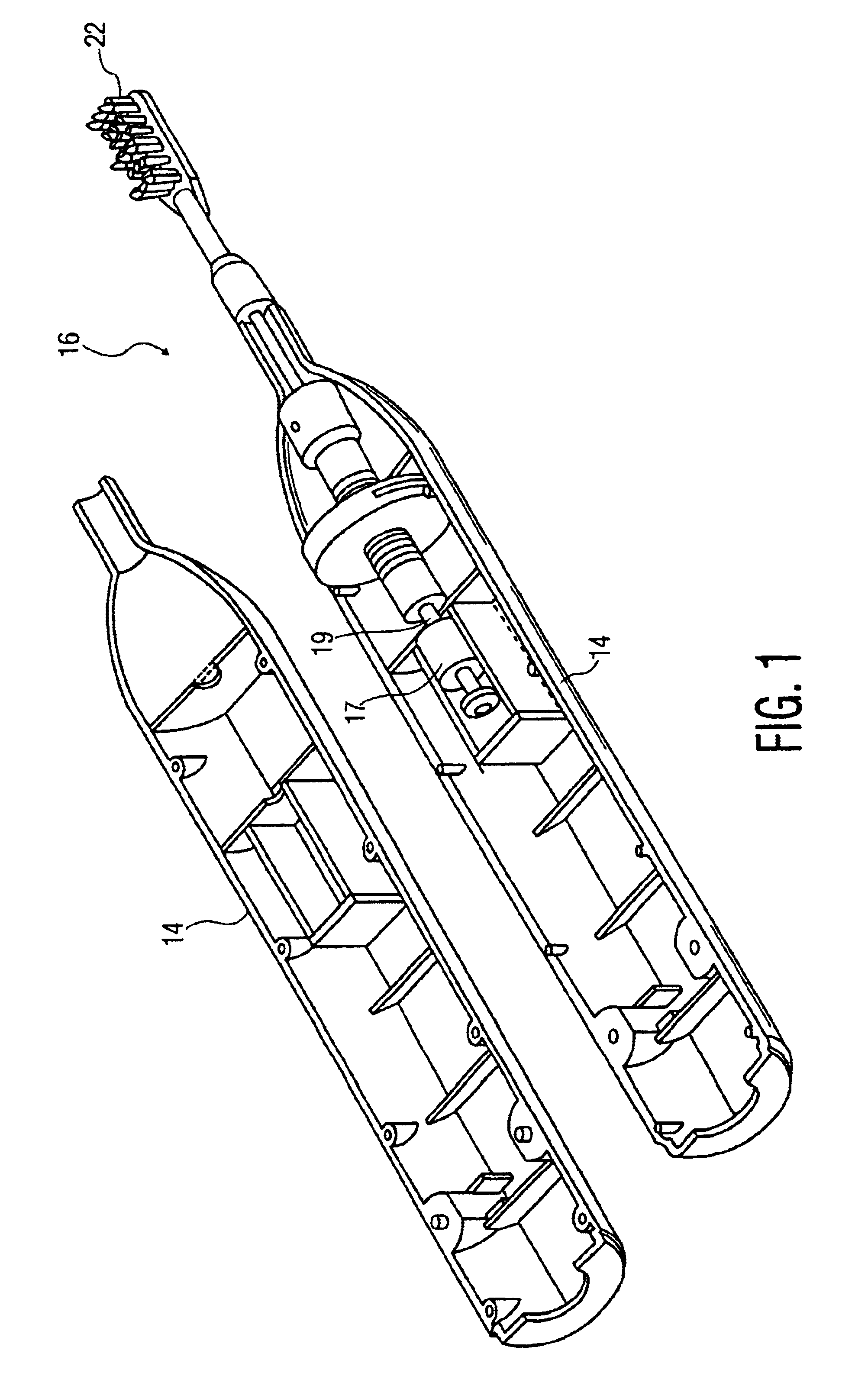
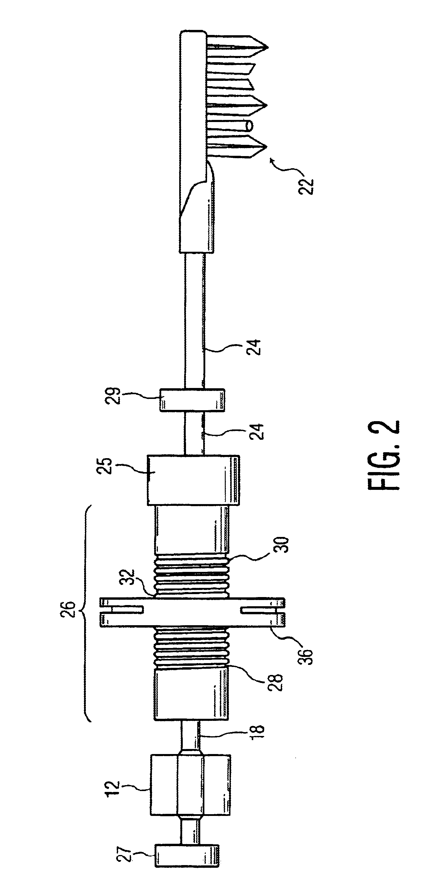
Referring to FIGS. 1 and 2, a small appliance motor 12 is mounted in a housing or handle 14 (shown split) of a power toothbrush 16. Although the present invention is described in the context of a power toothbrush for convenience of explanation and illustration, it should be understood that the system of the present invention could be used in other small appliances which drive other workpiece elements.

Motor 12 includes an armature 18 which is driven in a rotational mode in response to an electrical current provided from a battery 20 to a stator portion (not shown) of motor 12. Battery 20 will typically be a rechargeable battery, recharged via a charging base (not shown) in which the toothbrush is positioned when not in use. Such a charging base arrangement, for instance, is shown in U.S. Pat. No. 5,796,325, which is also owned by the assignee of the present invention.

At the other end of the drive system from motor 12 is a workpiece element, such as a brushhead 22. For the purposes of...


PUM


Abstract

The power toothbrush, which has a rotating brushhead movement, includes a housing with a motor mounted therein having an armature which in operation rotates through an arc of predetermined magnitude. The toothbrush also includes a brushhead mounted on a shaft which is connected to an output mass. A spring assembly couples the armature to the output mass, the spring assembly including two spring portions with a node point therebetween, wherein when the armature rotates, the brushhead moves in an opposite direction. The frequency of the movement of the armature is set equal to the resonant frequency of the spring coupling system and the output assembly.

Description

TECHNICAL FIELDThis invention relates generally to resonant drive systems for power toothbrushes and similar appliances, and more specifically concerns such systems having a rotational motor with a spring coupling arrangement from the motor to an output element, such as a brushhead.BACKGROUND OF THE INVENTIONPower toothbrushes are in general well known and encompass a wide variety of designs and physical arrangements. Some power toothbrushes have proven to be both effective and commercially successful. One example is the toothbrush shown in U.S. Pat. No. 5,189,751, which is owned by the assignee of the present invention.Many power toothbrushes have a rotary-type motion. Some have the capability of a 360° armature rotation, but due to design arrangements produce an oscillatory movement limited to a particular range of motion, i.e. a selected arcuate portion of 360°, in order to provide a more suitable brushing effect. Some of these rotary motion devices are mechanically driven, while...

Claims


Application Information

Patent Timeline
IPC IPC(8): A61C17/22A61C17/34A61C17/16
CPCA61C17/22A61C17/3481A61C17/3445
Inventor MILLER, KEVIN A.PACE, JOHN W.KOSTER, AAFKE G.
Owner KONINKLIJKE PHILIPS ELECTRONICS NV
Why Eureka
Try Eureka