Distributed optical fiber grating temperature detection system for high voltage electric power equipment

A technology of high-voltage power equipment and distributed optical fiber, which is applied in the field of measurement, can solve the problems of indistinguishable operation overtemperature, etc., and achieve the effects of strong anti-interference ability, large number of measurement points, and good reliability

Inactive Publication Date: 2005-06-29
淄博思科电子技术开发有限公司
View PDF5 Cites 34 Cited by
  • Summary
  • Abstract
  • Description
  • Claims
  • Application Information

AI Technical Summary

Problems solved by technology

[0007] However, since this technical solution uses multiple identical fiber gratings with identical grating constants as sensors, there is a problem that it is impossible to distinguish

Method used


Image

  • Distributed optical fiber grating temperature detection system for high voltage electric power equipment
  • Distributed optical fiber grating temperature detection system for high voltage electric power equipment
  • Distributed optical fiber grating temperature detection system for high voltage electric power equipment

Examples


Embodiment

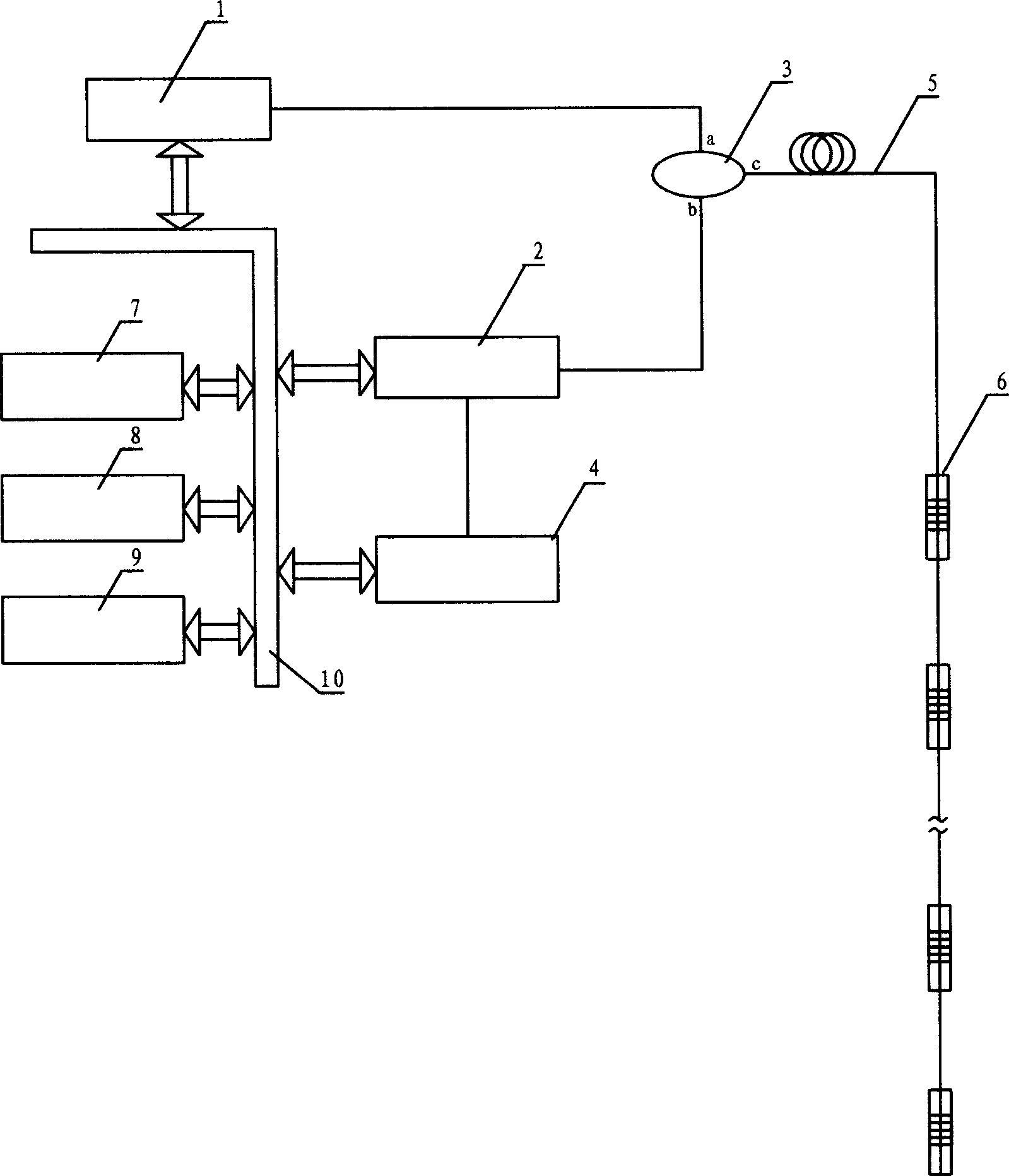
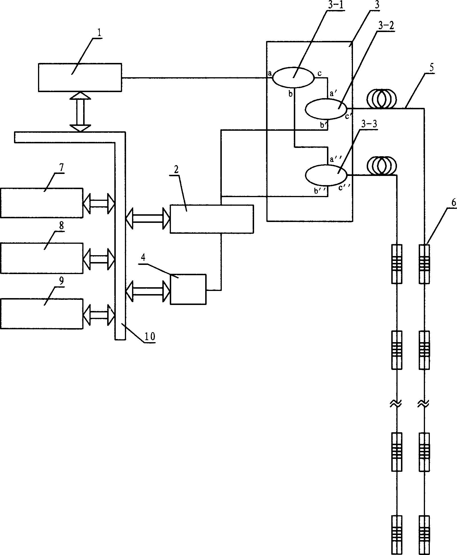
[0036] exist figure 1 The system structure shown and figure 2 The control and data processing unit shown is based on the use of image 3 In the shown optical path and circuit structure, the fiber coupler 3 includes at least three fiber couplers 3-1, 3-2 and 3-3.

[0037] A branch port a of the first fiber coupler 3-1 is optically connected to the broadband laser light source 1, and another branch port b of the first fiber coupler 3-1 is optically connected to a branch port a of the third fiber coupler 3-3. A combining port c of the fiber coupler is optically connected to a branching port a' of the second fiber coupler 3-2.

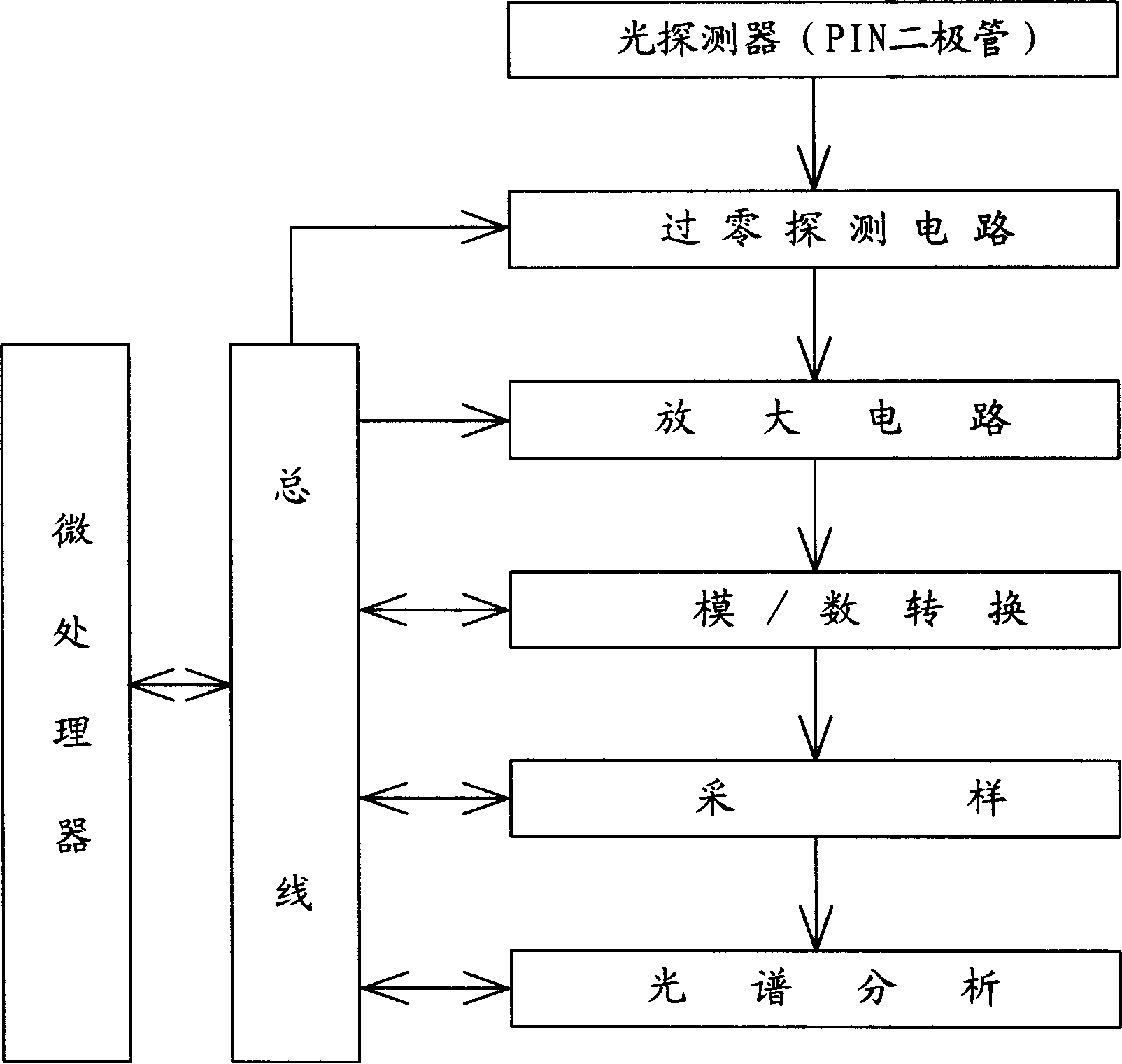
[0038] Another branch port b' of the second fiber coupler is optically connected to the input port of the photodetector module 4 through the tunable optical fiber filter 2, and its combined port c' is connected to at least two with different central wavelengths through the external optical fiber 5. The fiber grating sensors 6 are connected in series. ...


PUM


Abstract

It is a distribution light fiber and grating temperature measurement system used in high press electricity device, which belongs to measurement field and comprises wide band laser source, light fiber coupler, light fiber, light fiber and grating sensor, tunable fiber filter, and light detector. Setting light spectrum analysis unit and the unit of control and data process characterize it. Its laser source is connected with one sub-light of the light fiber coupler and the other sub-light is connected with input light end of the light detector through tunable light filter. The joining path end of the light coupler is connected in series with multiple fiber and grating sensor with different centers through light fiber. The laser source, tunable fiber filter, light detector are electrically connected with light spectrum analysis unit and the unit of control and data process through a bus.

Description

technical field [0001] The invention belongs to the field of measurement, and in particular relates to a temperature detection system for measuring the change of operating temperature or temperature rise at the joint of high-voltage electric equipment by detecting the change of the wavelength of light beam or light pulse. Background technique [0002] In the high-voltage main circuit of power system substations, distribution stations and power supply devices, at the joints where transformers, current transformers, voltage transformers, isolating switches, circuit breakers or other high-voltage switches are connected to power lines or high-voltage cables, due to power lines or The swing of the cable or the long-term power frequency vibration of the power equipment will often lead to the loosening of the connecting bolts, resulting in an increase in the contact resistance of the connecting part, which is affected by factors such as the degree of oxidation of the metal surface a...

Claims


Application Information

Patent Timeline
IPC IPC(8): G01D5/353G01K11/32
Inventor 耿玉桐陈飙
Owner 淄博思科电子技术开发有限公司
Why Eureka
Try Eureka